

Eroding and Dilating#
Goal#
In this tutorial you will learn how to:
Apply two very common morphological operators: Erosion and Dilation. For this purpose, you will use the following OpenCV functions:
Note
The explanation below belongs to the book Learning OpenCV by Bradski and Kaehler.
Morphological Operations#
In short: A set of operations that process images based on shapes. Morphological operations apply a structuring element to an input image and generate an output image.
The most basic morphological operations are: Erosion and Dilation. They have a wide array of uses, i.e. :
Removing noise
Isolation of individual elements and joining disparate elements in an image.
Finding of intensity bumps or holes in an image
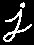
We will explain dilation and erosion briefly, using the following image as an example:
Dilation#
This operations consists of convolving an image \(A\) with some kernel (\(B\)), which can have any shape or size, usually a square or circle.
The kernel \(B\) has a defined anchor point, usually being the center of the kernel.
As the kernel \(B\) is scanned over the image, we compute the maximal pixel value overlapped by \(B\) and replace the image pixel in the anchor point position with that maximal value. As you can deduce, this maximizing operation causes bright regions within an image to “grow” (therefore the name dilation).
The dilatation operation is: \(\texttt{dst} (x,y) = \max _{(x',y'): \, \texttt{element} (x',y') \ne0 } \texttt{src} (x+x',y+y')\)
Take the above image as an example. Applying dilation we can get:
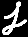
The bright area of the letter dilates around the black regions of the background.
Erosion#
This operation is the sister of dilation. It computes a local minimum over the area of given kernel.
As the kernel \(B\) is scanned over the image, we compute the minimal pixel value overlapped by \(B\) and replace the image pixel under the anchor point with that minimal value.
The erosion operation is: \(\texttt{dst} (x,y) = \min _{(x',y'): \, \texttt{element} (x',y') \ne0 } \texttt{src} (x+x',y+y')\)
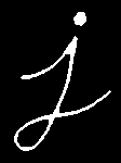
Analagously to the example for dilation, we can apply the erosion operator to the original image (shown above). You can see in the result below that the bright areas of the image get thinner, whereas the dark zones gets bigger.
Code#
This tutorial’s code is shown below. You can also download it here
#include "opencv2/imgproc.hpp"
#include "opencv2/highgui.hpp"
#include <iostream>

using namespace cv;
using namespace std;

/// Global variables
Mat src, erosion_dst, dilation_dst;

int erosion_elem = 0;
int erosion_size = 0;
int dilation_elem = 0;
int dilation_size = 0;
int const max_elem = 3;
int const max_kernel_size = 21;

void Erosion( int, void* );
void Dilation( int, void* );

int main( int argc, char** argv )
{
  /// Load an image
  CommandLineParser parser( argc, argv, "{@input | LinuxLogo.jpg | input image}" );
  src = imread( samples::findFile( parser.get<String>( "@input" ) ), IMREAD_COLOR );
  if( src.empty() )
  {
    cout << "Could not open or find the image!\n" << endl;
    cout << "Usage: " << argv[0] << " <Input image>" << endl;
    return -1;
  }

  /// Create windows
  namedWindow( "Erosion Demo", WINDOW_AUTOSIZE );
  namedWindow( "Dilation Demo", WINDOW_AUTOSIZE );
  moveWindow( "Dilation Demo", src.cols, 0 );

  /// Create Erosion Trackbar
  createTrackbar( "Element:\n 0: Rect \n 1: Cross \n 2: Ellipse \n 3: Diamond", "Erosion Demo",
          &erosion_elem, max_elem,
          Erosion );

  createTrackbar( "Kernel size:\n 2n +1", "Erosion Demo",
          &erosion_size, max_kernel_size,
          Erosion );

  /// Create Dilation Trackbar
  createTrackbar( "Element:\n 0: Rect \n 1: Cross \n 2: Ellipse \n 3: Diamond", "Dilation Demo",
          &dilation_elem, max_elem,
          Dilation );

  createTrackbar( "Kernel size:\n 2n +1", "Dilation Demo",
          &dilation_size, max_kernel_size,
          Dilation );

  /// Default start
  Erosion( 0, 0 );
  Dilation( 0, 0 );

  waitKey(0);
  return 0;
}

void Erosion( int, void* )
{
  int erosion_type = 0;
  if( erosion_elem == 0 ){ erosion_type = MORPH_RECT; }
  else if( erosion_elem == 1 ){ erosion_type = MORPH_CROSS; }
  else if( erosion_elem == 2) { erosion_type = MORPH_ELLIPSE; }
  else if( erosion_elem == 3) { erosion_type = MORPH_DIAMOND; }

  Mat element = getStructuringElement( erosion_type,
                       Size( 2*erosion_size + 1, 2*erosion_size+1 ),
                       Point( erosion_size, erosion_size ) );

  /// Apply the erosion operation
  erode( src, erosion_dst, element );
  imshow( "Erosion Demo", erosion_dst );
}

void Dilation( int, void* )
{
  int dilation_type = 0;
  if( dilation_elem == 0 ){ dilation_type = MORPH_RECT; }
  else if( dilation_elem == 1 ){ dilation_type = MORPH_CROSS; }
  else if( dilation_elem == 2) { dilation_type = MORPH_ELLIPSE; }
  else if( dilation_elem == 3) { dilation_type = MORPH_DIAMOND; }

  Mat element = getStructuringElement( dilation_type,
                       Size( 2*dilation_size + 1, 2*dilation_size+1 ),
                       Point( dilation_size, dilation_size ) );

  /// Apply the dilation operation
  dilate( src, dilation_dst, element );
  imshow( "Dilation Demo", dilation_dst );
}
This tutorial’s code is shown below. You can also download it here
import java.awt.BorderLayout;
import java.awt.Container;
import java.awt.Image;
import java.awt.event.ActionEvent;
import java.awt.event.ActionListener;

import javax.swing.BoxLayout;
import javax.swing.ImageIcon;
import javax.swing.JComboBox;
import javax.swing.JFrame;
import javax.swing.JLabel;
import javax.swing.JPanel;
import javax.swing.JSlider;
import javax.swing.event.ChangeEvent;
import javax.swing.event.ChangeListener;

import org.opencv.core.Core;
import org.opencv.core.Mat;
import org.opencv.core.Point;
import org.opencv.core.Size;
import org.opencv.highgui.HighGui;
import org.opencv.imgcodecs.Imgcodecs;
import org.opencv.imgproc.Imgproc;

public class MorphologyDemo1 {
    private static final String[] ELEMENT_TYPE = { "Rectangle", "Cross", "Ellipse", "Diamond" };
    private static final String[] MORPH_OP = { "Erosion", "Dilatation" };
    private static final int MAX_KERNEL_SIZE = 21;
    private Mat matImgSrc;
    private Mat matImgDst = new Mat();
    private int elementType = Imgproc.MORPH_RECT;
    private int kernelSize = 0;
    private boolean doErosion = true;
    private JFrame frame;
    private JLabel imgLabel;

    public MorphologyDemo1(String[] args) {
        String imagePath = args.length > 0 ? args[0] : "../data/LinuxLogo.jpg";
        matImgSrc = Imgcodecs.imread(imagePath);
        if (matImgSrc.empty()) {
            System.out.println("Empty image: " + imagePath);
            System.exit(0);
        }

        // Create and set up the window.
        frame = new JFrame("Erosion and dilatation demo");
        frame.setDefaultCloseOperation(JFrame.EXIT_ON_CLOSE);
        // Set up the content pane.
        Image img = HighGui.toBufferedImage(matImgSrc);
        addComponentsToPane(frame.getContentPane(), img);
        // Use the content pane's default BorderLayout. No need for
        // setLayout(new BorderLayout());
        // Display the window.
        frame.pack();
        frame.setVisible(true);
    }

    private void addComponentsToPane(Container pane, Image img) {
        if (!(pane.getLayout() instanceof BorderLayout)) {
            pane.add(new JLabel("Container doesn't use BorderLayout!"));
            return;
        }

        JPanel sliderPanel = new JPanel();
        sliderPanel.setLayout(new BoxLayout(sliderPanel, BoxLayout.PAGE_AXIS));

        JComboBox<String> elementTypeBox = new JComboBox<>(ELEMENT_TYPE);
        elementTypeBox.addActionListener(new ActionListener() {
            @Override
            public void actionPerformed(ActionEvent e) {
                @SuppressWarnings("unchecked")
                JComboBox<String> cb = (JComboBox<String>)e.getSource();
                if (cb.getSelectedIndex() == 0) {
                    elementType = Imgproc.MORPH_RECT;
                } else if (cb.getSelectedIndex() == 1) {
                    elementType = Imgproc.MORPH_CROSS;
                } else if (cb.getSelectedIndex() == 2) {
                    elementType = Imgproc.MORPH_ELLIPSE;
                } else if (cb.getSelectedIndex() == 3) {
                    elementType = Imgproc.MORPH_DIAMOND;
                }
                update();
            }
        });
        sliderPanel.add(elementTypeBox);

        sliderPanel.add(new JLabel("Kernel size: 2n + 1"));
        JSlider slider = new JSlider(0, MAX_KERNEL_SIZE, 0);
        slider.setMajorTickSpacing(5);
        slider.setMinorTickSpacing(5);
        slider.setPaintTicks(true);
        slider.setPaintLabels(true);
        slider.addChangeListener(new ChangeListener() {
            @Override
            public void stateChanged(ChangeEvent e) {
                JSlider source = (JSlider) e.getSource();
                kernelSize = source.getValue();
                update();
            }
        });
        sliderPanel.add(slider);

        JComboBox<String> morphOpBox = new JComboBox<>(MORPH_OP);
        morphOpBox.addActionListener(new ActionListener() {
            @Override
            public void actionPerformed(ActionEvent e) {
                @SuppressWarnings("unchecked")
                JComboBox<String> cb = (JComboBox<String>)e.getSource();
                doErosion = cb.getSelectedIndex() == 0;
                update();
            }
        });
        sliderPanel.add(morphOpBox);

        pane.add(sliderPanel, BorderLayout.PAGE_START);
        imgLabel = new JLabel(new ImageIcon(img));
        pane.add(imgLabel, BorderLayout.CENTER);
    }

    private void update() {
        Mat element = Imgproc.getStructuringElement(elementType, new Size(2 * kernelSize + 1, 2 * kernelSize + 1),
                new Point(kernelSize, kernelSize));

        if (doErosion) {
            Imgproc.erode(matImgSrc, matImgDst, element);
        } else {
            Imgproc.dilate(matImgSrc, matImgDst, element);
        }
        Image img = HighGui.toBufferedImage(matImgDst);
        imgLabel.setIcon(new ImageIcon(img));
        frame.repaint();
    }

    public static void main(String[] args) {
        // Load the native OpenCV library
        System.loadLibrary(Core.NATIVE_LIBRARY_NAME);

        // Schedule a job for the event dispatch thread:
        // creating and showing this application's GUI.
        javax.swing.SwingUtilities.invokeLater(new Runnable() {
            @Override
            public void run() {
                new MorphologyDemo1(args);
            }
        });
    }
}
This tutorial’s code is shown below. You can also download it here
from __future__ import print_function
import cv2 as cv
import numpy as np
import argparse

src = None
erosion_size = 0
max_elem = 3
max_kernel_size = 21
title_trackbar_element_shape = 'Element:\n 0: Rect \n 1: Cross \n 2: Ellipse \n 3: Diamond'
title_trackbar_kernel_size = 'Kernel size:\n 2n +1'
title_erosion_window = 'Erosion Demo'
title_dilation_window = 'Dilation Demo'

def main(image):
    global src
    src = cv.imread(cv.samples.findFile(image))
    if src is None:
        print('Could not open or find the image: ', image)
        exit(0)

    cv.namedWindow(title_erosion_window)
    cv.createTrackbar(title_trackbar_element_shape, title_erosion_window, 0, max_elem, erosion)
    cv.createTrackbar(title_trackbar_kernel_size, title_erosion_window, 0, max_kernel_size, erosion)

    cv.namedWindow(title_dilation_window)
    cv.createTrackbar(title_trackbar_element_shape, title_dilation_window, 0, max_elem, dilatation)
    cv.createTrackbar(title_trackbar_kernel_size, title_dilation_window, 0, max_kernel_size, dilatation)

    erosion(0)
    dilatation(0)
    cv.waitKey()

# optional mapping of values with morphological shapes
def morph_shape(val):
    if val == 0:
        return cv.MORPH_RECT
    elif val == 1:
        return cv.MORPH_CROSS
    elif val == 2:
        return cv.MORPH_ELLIPSE
    elif val == 3:
        return cv.MORPH_DIAMOND

def erosion(val):
    erosion_size = cv.getTrackbarPos(title_trackbar_kernel_size, title_erosion_window)
    erosion_shape = morph_shape(cv.getTrackbarPos(title_trackbar_element_shape, title_erosion_window))

    element = cv.getStructuringElement(erosion_shape, (2 * erosion_size + 1, 2 * erosion_size + 1),
                                       (erosion_size, erosion_size))
    erosion_dst = cv.erode(src, element)
    cv.imshow(title_erosion_window, erosion_dst)

def dilatation(val):
    dilatation_size = cv.getTrackbarPos(title_trackbar_kernel_size, title_dilation_window)
    dilation_shape = morph_shape(cv.getTrackbarPos(title_trackbar_element_shape, title_dilation_window))

    element = cv.getStructuringElement(dilation_shape, (2 * dilatation_size + 1, 2 * dilatation_size + 1),
                                       (dilatation_size, dilatation_size))
    dilatation_dst = cv.dilate(src, element)
    cv.imshow(title_dilation_window, dilatation_dst)

if __name__ == "__main__":
    parser = argparse.ArgumentParser(description='Code for Eroding and Dilating tutorial.')
    parser.add_argument('--input', help='Path to input image.', default='LinuxLogo.jpg')
    args = parser.parse_args()

    main(args.input)
Explanation#
Most of the material shown here is trivial (if you have any doubt, please refer to the tutorials in previous sections). Let’s check the general structure of the C++ program:
int main( int argc, char** argv )
{
  /// Load an image
  CommandLineParser parser( argc, argv, "{@input | LinuxLogo.jpg | input image}" );
  src = imread( samples::findFile( parser.get<String>( "@input" ) ), IMREAD_COLOR );
  if( src.empty() )
  {
    cout << "Could not open or find the image!\n" << endl;
    cout << "Usage: " << argv[0] << " <Input image>" << endl;
    return -1;
  }

  /// Create windows
  namedWindow( "Erosion Demo", WINDOW_AUTOSIZE );
  namedWindow( "Dilation Demo", WINDOW_AUTOSIZE );
  moveWindow( "Dilation Demo", src.cols, 0 );

  /// Create Erosion Trackbar
  createTrackbar( "Element:\n 0: Rect \n 1: Cross \n 2: Ellipse \n 3: Diamond", "Erosion Demo",
          &erosion_elem, max_elem,
          Erosion );

  createTrackbar( "Kernel size:\n 2n +1", "Erosion Demo",
          &erosion_size, max_kernel_size,
          Erosion );

  /// Create Dilation Trackbar
  createTrackbar( "Element:\n 0: Rect \n 1: Cross \n 2: Ellipse \n 3: Diamond", "Dilation Demo",
          &dilation_elem, max_elem,
          Dilation );

  createTrackbar( "Kernel size:\n 2n +1", "Dilation Demo",
          &dilation_size, max_kernel_size,
          Dilation );

  /// Default start
  Erosion( 0, 0 );
  Dilation( 0, 0 );

  waitKey(0);
  return 0;
}
Load an image (can be BGR or grayscale)
Create two windows (one for dilation output, the other for erosion)
Create a set of two Trackbars for each operation:
The first trackbar “Element” returns either erosion_elem or dilation_elem
The second trackbar “Kernel size” return erosion_size or dilation_size for the corresponding operation.
Call once erosion and dilation to show the initial image.
Every time we move any slider, the user’s function Erosion or Dilation will be called and it will update the output image based on the current trackbar values.
Let’s analyze these two functions:
The erosion function (CPP)
void Erosion( int, void* )
{
  int erosion_type = 0;
  if( erosion_elem == 0 ){ erosion_type = MORPH_RECT; }
  else if( erosion_elem == 1 ){ erosion_type = MORPH_CROSS; }
  else if( erosion_elem == 2) { erosion_type = MORPH_ELLIPSE; }
  else if( erosion_elem == 3) { erosion_type = MORPH_DIAMOND; }

  Mat element = getStructuringElement( erosion_type,
                       Size( 2*erosion_size + 1, 2*erosion_size+1 ),
                       Point( erosion_size, erosion_size ) );

  /// Apply the erosion operation
  erode( src, erosion_dst, element );
  imshow( "Erosion Demo", erosion_dst );
}
The function that performs the erosion operation is cv::erode . As we can see, it receives three arguments:
src: The source image
erosion_dst: The output image
element: This is the kernel we will use to perform the operation. If we do not specify, the default is a simple
3x3matrix. Otherwise, we can specify its shape. For this, we need to use the function cv::getStructuringElement :Mat element = getStructuringElement( erosion_type, Size( 2*erosion_size + 1, 2*erosion_size+1 ), Point( erosion_size, erosion_size ) );
We can choose any of three shapes for our kernel:
Rectangular box: MORPH_RECT
Cross: MORPH_CROSS
Ellipse: MORPH_ELLIPSE
Diamond: MORPH_DIAMOND
Then, we just have to specify the size of our kernel and the anchor point. If not specified, it is assumed to be in the center.
That is all. We are ready to perform the erosion of our image.
The dilation function (CPP)
The code is below. As you can see, it is completely similar to the snippet of code for erosion. Here we also have the option of defining our kernel, its anchor point and the size of the operator to be used.
void Dilation( int, void* )
{
  int dilation_type = 0;
  if( dilation_elem == 0 ){ dilation_type = MORPH_RECT; }
  else if( dilation_elem == 1 ){ dilation_type = MORPH_CROSS; }
  else if( dilation_elem == 2) { dilation_type = MORPH_ELLIPSE; }
  else if( dilation_elem == 3) { dilation_type = MORPH_DIAMOND; }

  Mat element = getStructuringElement( dilation_type,
                       Size( 2*dilation_size + 1, 2*dilation_size+1 ),
                       Point( dilation_size, dilation_size ) );

  /// Apply the dilation operation
  dilate( src, dilation_dst, element );
  imshow( "Dilation Demo", dilation_dst );
}
Most of the material shown here is trivial (if you have any doubt, please refer to the tutorials in previous sections). Let’s check however the general structure of the java class. There are 4 main parts in the java class:
the class constructor which setups the window that will be filled with window components
the
addComponentsToPanemethod, which fills out the windowthe
updatemethod, which determines what happens when the user changes any valuethe
mainmethod, which is the entry point of the program
In this tutorial we will focus on the addComponentsToPane and update methods. However, for completion the
steps followed in the constructor are:
Load an image (can be BGR or grayscale)
Create a window
Add various control components with
addComponentsToPaneshow the window
The components were added by the following method:
private void addComponentsToPane(Container pane, Image img) {
    if (!(pane.getLayout() instanceof BorderLayout)) {
        pane.add(new JLabel("Container doesn't use BorderLayout!"));
        return;
    }

    JPanel sliderPanel = new JPanel();
    sliderPanel.setLayout(new BoxLayout(sliderPanel, BoxLayout.PAGE_AXIS));

    JComboBox<String> elementTypeBox = new JComboBox<>(ELEMENT_TYPE);
    elementTypeBox.addActionListener(new ActionListener() {
        @Override
        public void actionPerformed(ActionEvent e) {
            @SuppressWarnings("unchecked")
            JComboBox<String> cb = (JComboBox<String>)e.getSource();
            if (cb.getSelectedIndex() == 0) {
                elementType = Imgproc.MORPH_RECT;
            } else if (cb.getSelectedIndex() == 1) {
                elementType = Imgproc.MORPH_CROSS;
            } else if (cb.getSelectedIndex() == 2) {
                elementType = Imgproc.MORPH_ELLIPSE;
            } else if (cb.getSelectedIndex() == 3) {
                elementType = Imgproc.MORPH_DIAMOND;
            }
            update();
        }
    });
    sliderPanel.add(elementTypeBox);

    sliderPanel.add(new JLabel("Kernel size: 2n + 1"));
    JSlider slider = new JSlider(0, MAX_KERNEL_SIZE, 0);
    slider.setMajorTickSpacing(5);
    slider.setMinorTickSpacing(5);
    slider.setPaintTicks(true);
    slider.setPaintLabels(true);
    slider.addChangeListener(new ChangeListener() {
        @Override
        public void stateChanged(ChangeEvent e) {
            JSlider source = (JSlider) e.getSource();
            kernelSize = source.getValue();
            update();
        }
    });
    sliderPanel.add(slider);

    JComboBox<String> morphOpBox = new JComboBox<>(MORPH_OP);
    morphOpBox.addActionListener(new ActionListener() {
        @Override
        public void actionPerformed(ActionEvent e) {
            @SuppressWarnings("unchecked")
            JComboBox<String> cb = (JComboBox<String>)e.getSource();
            doErosion = cb.getSelectedIndex() == 0;
            update();
        }
    });
    sliderPanel.add(morphOpBox);

    pane.add(sliderPanel, BorderLayout.PAGE_START);
    imgLabel = new JLabel(new ImageIcon(img));
    pane.add(imgLabel, BorderLayout.CENTER);
}
In short we
create a panel for the sliders
create a combo box for the element types
create a slider for the kernel size
create a combo box for the morphology function to use (erosion or dilation)
The action and state changed listeners added call at the end the update method which updates
the image based on the current slider values. So every time we move any slider, the update method is triggered.
Updating the image (Java)
To update the image we used the following implementation:
private void update() {
    Mat element = Imgproc.getStructuringElement(elementType, new Size(2 * kernelSize + 1, 2 * kernelSize + 1),
            new Point(kernelSize, kernelSize));

    if (doErosion) {
        Imgproc.erode(matImgSrc, matImgDst, element);
    } else {
        Imgproc.dilate(matImgSrc, matImgDst, element);
    }
    Image img = HighGui.toBufferedImage(matImgDst);
    imgLabel.setIcon(new ImageIcon(img));
    frame.repaint();
}
In other words we
get the structuring element the user chose
execute the erosion or dilation function based on
doErosionreload the image with the morphology applied
repaint the frame
Let’s analyze the erode and dilate methods:
The erosion method (Java)
Imgproc.erode(matImgSrc, matImgDst, element);
The function that performs the erosion operation is cv::erode . As we can see, it receives three arguments:
src: The source image
erosion_dst: The output image
element: This is the kernel we will use to perform the operation. For specifying the shape, we need to use the function cv::getStructuringElement :
We can choose any of three shapes for our kernel:
Rectangular box: Imgproc.SHAPE_RECT
Cross: Imgproc.SHAPE_CROSS
Ellipse: Imgproc.SHAPE_ELLIPSE
Together with the shape we specify the size of our kernel and the anchor point. If the anchor point is not specified, it is assumed to be in the center.
That is all. We are ready to perform the erosion of our image.
The dilation function (Java)
The code is below. As you can see, it is completely similar to the snippet of code for erosion. Here we also have the option of defining our kernel, its anchor point and the size of the operator to be used.
Imgproc.dilate(matImgSrc, matImgDst, element);
Most of the material shown here is trivial (if you have any doubt, please refer to the tutorials in previous sections). Let’s check the general structure of the python script:
def main(image):
    global src
    src = cv.imread(cv.samples.findFile(image))
    if src is None:
        print('Could not open or find the image: ', image)
        exit(0)

    cv.namedWindow(title_erosion_window)
    cv.createTrackbar(title_trackbar_element_shape, title_erosion_window, 0, max_elem, erosion)
    cv.createTrackbar(title_trackbar_kernel_size, title_erosion_window, 0, max_kernel_size, erosion)

    cv.namedWindow(title_dilation_window)
    cv.createTrackbar(title_trackbar_element_shape, title_dilation_window, 0, max_elem, dilatation)
    cv.createTrackbar(title_trackbar_kernel_size, title_dilation_window, 0, max_kernel_size, dilatation)

    erosion(0)
    dilatation(0)
    cv.waitKey()
Load an image (can be BGR or grayscale)
Create two windows (one for erosion output, the other for dilation) with a set of trackbars each
The first trackbar “Element” returns the value for the morphological type that will be mapped (1 = rectangle, 2 = cross, 3 = ellipse)
The second trackbar “Kernel size” returns the size of the element for the corresponding operation
Call once erosion and dilation to show the initial image
Every time we move any slider, the user’s function erosion or dilation will be called and it will update the output image based on the current trackbar values.
Let’s analyze these two functions:
The erosion function (Python)
def erosion(val):
    erosion_size = cv.getTrackbarPos(title_trackbar_kernel_size, title_erosion_window)
    erosion_shape = morph_shape(cv.getTrackbarPos(title_trackbar_element_shape, title_erosion_window))

    element = cv.getStructuringElement(erosion_shape, (2 * erosion_size + 1, 2 * erosion_size + 1),
                                       (erosion_size, erosion_size))
    erosion_dst = cv.erode(src, element)
    cv.imshow(title_erosion_window, erosion_dst)
The function that performs the erosion operation is cv::erode . As we can see, it receives two arguments and returns the processed image:
src: The source image
element: The kernel we will use to perform the operation. We can specify its shape by using the function cv::getStructuringElement :
element = cv.getStructuringElement(erosion_shape, (2 * erosion_size + 1, 2 * erosion_size + 1),
                                   (erosion_size, erosion_size))
We can choose any of three shapes for our kernel:
Rectangular box: MORPH_RECT
Cross: MORPH_CROSS
Ellipse: MORPH_ELLIPSE
Diamond: MORPH_DIAMOND
Then, we just have to specify the size of our kernel and the anchor point. If the anchor point not specified, it is assumed to be in the center.
That is all. We are ready to perform the erosion of our image.
The dilation function (Python)
The code is below. As you can see, it is completely similar to the snippet of code for erosion. Here we also have the option of defining our kernel, its anchor point and the size of the operator to be used.
def dilatation(val):
    dilatation_size = cv.getTrackbarPos(title_trackbar_kernel_size, title_dilation_window)
    dilation_shape = morph_shape(cv.getTrackbarPos(title_trackbar_element_shape, title_dilation_window))

    element = cv.getStructuringElement(dilation_shape, (2 * dilatation_size + 1, 2 * dilatation_size + 1),
                                       (dilatation_size, dilatation_size))
    dilatation_dst = cv.dilate(src, element)
    cv.imshow(title_dilation_window, dilatation_dst)
Note
Additionally, there are further parameters that allow you to perform multiple erosions/dilations (iterations) at once and also set the border type and value. However, We haven’t used those in this simple tutorial. You can check out the reference for more details.
Results#
Compile the code above and execute it (or run the script if using python) with an image as argument. If you do not provide an image as argument the default sample image (LinuxLogo.jpg) will be used.

For instance, using this image:
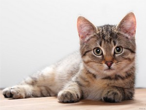
We get the results below. Varying the indices in the Trackbars give different output images, naturally. Try them out! You can even try to add a third Trackbar to control the number of iterations.
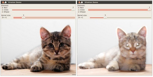 (depending on the programming language the output might vary a little or be only 1 window)