OpenCV  4.9.0-dev
Open Source Computer Vision
Loading...
Searching...
No Matches
Detection of ArUco boards

Prev Tutorial: Detection of ArUco Markers

Original authors Sergio Garrido, Alexander Panov
Compatibility OpenCV >= 4.7.0

An ArUco board is a set of markers that acts like a single marker in the sense that it provides a single pose for the camera.

The most popular board is the one with all the markers in the same plane, since it can be easily printed:

However, boards are not limited to this arrangement and can represent any 2d or 3d layout.

The difference between a board and a set of independent markers is that the relative position between the markers in the board is known a priori. This allows that the corners of all the markers can be used for estimating the pose of the camera respect to the whole board.

When you use a set of independent markers, you can estimate the pose for each marker individually, since you dont know the relative position of the markers in the environment.

The main benefits of using boards are:

  • The pose estimation is much more versatile. Only some markers are necessary to perform pose estimation. Thus, the pose can be calculated even in the presence of occlusions or partial views.
  • The obtained pose is usually more accurate since a higher amount of point correspondences (marker corners) are employed.

Board Detection

A board detection is similar to the standard marker detection. The only difference is in the pose estimation step. In fact, to use marker boards, a standard marker detection should be done before estimating the board pose.

To perform pose estimation for boards, you should use solvePnP() function, as shown below in the samples/cpp/tutorial_code/objectDetection/detect_board.cpp.

int markersX = parser.get<int>("w");
int markersY = parser.get<int>("h");
float markerLength = parser.get<float>("l");
float markerSeparation = parser.get<float>("s");
bool showRejected = parser.has("r");
bool refindStrategy = parser.has("rs");
int camId = parser.get<int>("ci");
Mat camMatrix, distCoeffs;
readCameraParamsFromCommandLine(parser, camMatrix, distCoeffs);
aruco::DetectorParameters detectorParams;
detectorParams.cornerRefinementMethod = aruco::CORNER_REFINE_SUBPIX; // do corner refinement in markers
readDetectorParamsFromCommandLine(parser, detectorParams);
String video;
if(parser.has("v")) {
video = parser.get<String>("v");
}
if(!parser.check()) {
parser.printErrors();
return 0;
}
aruco::Dictionary dictionary = aruco::getPredefinedDictionary(cv::aruco::DICT_4X4_50);
readDictionatyFromCommandLine(parser, dictionary);
aruco::ArucoDetector detector(dictionary, detectorParams);
VideoCapture inputVideo;
int waitTime;
if(!video.empty()) {
inputVideo.open(video);
waitTime = 0;
} else {
inputVideo.open(camId);
waitTime = 10;
}
float axisLength = 0.5f * ((float)min(markersX, markersY) * (markerLength + markerSeparation) +
markerSeparation);
// Create GridBoard object
aruco::GridBoard board(Size(markersX, markersY), markerLength, markerSeparation, dictionary);
// Also you could create Board object
//vector<vector<Point3f> > objPoints; // array of object points of all the marker corners in the board
//vector<int> ids; // vector of the identifiers of the markers in the board
//aruco::Board board(objPoints, dictionary, ids);
double totalTime = 0;
int totalIterations = 0;
while(inputVideo.grab()) {
Mat image, imageCopy;
inputVideo.retrieve(image);
double tick = (double)getTickCount();
vector<int> ids;
vector<vector<Point2f>> corners, rejected;
Vec3d rvec, tvec;
// Detect markers
detector.detectMarkers(image, corners, ids, rejected);
// Refind strategy to detect more markers
if(refindStrategy)
detector.refineDetectedMarkers(image, board, corners, ids, rejected, camMatrix,
distCoeffs);
// Estimate board pose
int markersOfBoardDetected = 0;
if(!ids.empty()) {
// Get object and image points for the solvePnP function
cv::Mat objPoints, imgPoints;
board.matchImagePoints(corners, ids, objPoints, imgPoints);
// Find pose
cv::solvePnP(objPoints, imgPoints, camMatrix, distCoeffs, rvec, tvec);
markersOfBoardDetected = (int)objPoints.total() / 4;
}
double currentTime = ((double)getTickCount() - tick) / getTickFrequency();
totalTime += currentTime;
totalIterations++;
if(totalIterations % 30 == 0) {
cout << "Detection Time = " << currentTime * 1000 << " ms "
<< "(Mean = " << 1000 * totalTime / double(totalIterations) << " ms)" << endl;
}
// Draw results
image.copyTo(imageCopy);
if(!ids.empty()) {
aruco::drawDetectedMarkers(imageCopy, corners, ids);
}
if(showRejected && !rejected.empty())
aruco::drawDetectedMarkers(imageCopy, rejected, noArray(), Scalar(100, 0, 255));
if(markersOfBoardDetected > 0)
cv::drawFrameAxes(imageCopy, camMatrix, distCoeffs, rvec, tvec, axisLength);
imshow("out", imageCopy);
char key = (char)waitKey(waitTime);
if(key == 27) break;
n-dimensional dense array class
Definition mat.hpp:812
size_t total() const
Returns the total number of array elements.
bool solvePnP(InputArray objectPoints, InputArray imagePoints, InputArray cameraMatrix, InputArray distCoeffs, OutputArray rvec, OutputArray tvec, bool useExtrinsicGuess=false, int flags=SOLVEPNP_ITERATIVE)
Finds an object pose from 3D-2D point correspondences.
void drawFrameAxes(InputOutputArray image, InputArray cameraMatrix, InputArray distCoeffs, InputArray rvec, InputArray tvec, float length, int thickness=3)
Draw axes of the world/object coordinate system from pose estimation.
void min(InputArray src1, InputArray src2, OutputArray dst)
Calculates per-element minimum of two arrays or an array and a scalar.
Size2i Size
Definition types.hpp:370
Vec< double, 3 > Vec3d
Definition matx.hpp:464
Scalar_< double > Scalar
Definition types.hpp:702
InputOutputArray noArray()
double getTickFrequency()
Returns the number of ticks per second.
int64 getTickCount()
Returns the number of ticks.
void imshow(const String &winname, InputArray mat)
Displays an image in the specified window.
int waitKey(int delay=0)
Waits for a pressed key.
@ DICT_4X4_50
4x4 bits, minimum hamming distance between any two codes = 4, 50 codes
Definition aruco_dictionary.hpp:100

The parameters are:

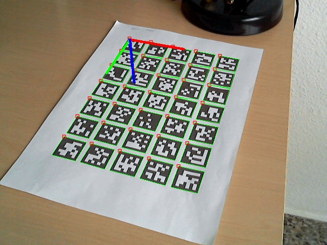
  • objPoints, imgPoints object and image points, matched with cv::aruco::GridBoard::matchImagePoints() which, in turn, takes as input markerCorners and markerIds structures of detected markers from cv::aruco::ArucoDetector::detectMarkers() function.
  • board the cv::aruco::Board object that defines the board layout and its ids
  • cameraMatrix and distCoeffs: camera calibration parameters necessary for pose estimation.
  • rvec and tvec: estimated pose of the board. If not empty then treated as initial guess.
  • The function returns the total number of markers employed for estimating the board pose.

The drawFrameAxes() function can be used to check the obtained pose. For instance:

Board with axis

And this is another example with the board partially occluded:

Board with occlusions

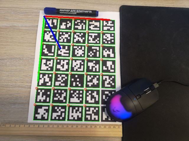
As it can be observed, although some markers have not been detected, the board pose can still be estimated from the rest of markers.

Sample video:

A full working example is included in the detect_board.cpp inside the samples/cpp/tutorial_code/objectDetection/.

The samples now take input via command line via the cv::CommandLineParser. For this file the example parameters will look like:

-w=5 -h=7 -l=100 -s=10
-v=/path_to_opencv/opencv/doc/tutorials/objdetect/aruco_board_detection/gboriginal.jpg
-c=/path_to_opencv/opencv/samples/cpp/tutorial_code/objectDetection/tutorial_camera_params.yml
-cd=/path_to_opencv/opencv/samples/cpp/tutorial_code/objectDetection/tutorial_dict.yml

Parameters for detect_board.cpp:

const char* keys =
"{w | | Number of squares in X direction }"
"{h | | Number of squares in Y direction }"
"{l | | Marker side length (in pixels) }"
"{s | | Separation between two consecutive markers in the grid (in pixels)}"
"{d | | dictionary: DICT_4X4_50=0, DICT_4X4_100=1, DICT_4X4_250=2,"
"DICT_4X4_1000=3, DICT_5X5_50=4, DICT_5X5_100=5, DICT_5X5_250=6, DICT_5X5_1000=7, "
"DICT_6X6_50=8, DICT_6X6_100=9, DICT_6X6_250=10, DICT_6X6_1000=11, DICT_7X7_50=12,"
"DICT_7X7_100=13, DICT_7X7_250=14, DICT_7X7_1000=15, DICT_ARUCO_ORIGINAL = 16}"
"{cd | | Input file with custom dictionary }"
"{c | | Output file with calibrated camera parameters }"
"{v | | Input from video or image file, if omitted, input comes from camera }"
"{ci | 0 | Camera id if input doesnt come from video (-v) }"
"{dp | | File of marker detector parameters }"
"{rs | | Apply refind strategy }"
"{r | | show rejected candidates too }";
}

Grid Board

Creating the cv::aruco::Board object requires specifying the corner positions for each marker in the environment. However, in many cases, the board will be just a set of markers in the same plane and in a grid layout, so it can be easily printed and used.

Fortunately, the aruco module provides the basic functionality to create and print these types of markers easily.

The cv::aruco::GridBoard class is a specialized class that inherits from the cv::aruco::Board class and which represents a Board with all the markers in the same plane and in a grid layout, as in the following image:

Image with aruco board

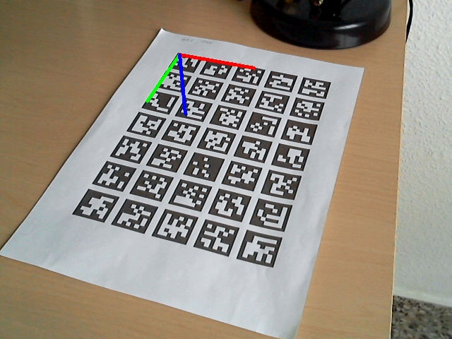
Concretely, the coordinate system in a grid board is positioned in the board plane, centered in the bottom left corner of the board and with the Z pointing out, like in the following image (X:red, Y:green, Z:blue):

Board with axis

A cv::aruco::GridBoard object can be defined using the following parameters:

  • Number of markers in the X direction.
  • Number of markers in the Y direction.
  • Length of the marker side.
  • Length of the marker separation.
  • The dictionary of the markers.
  • Ids of all the markers (X*Y markers).

This object can be easily created from these parameters using the cv::aruco::GridBoard constructor:

aruco::GridBoard board(Size(markersX, markersY), markerLength, markerSeparation, dictionary);
  • The first and second parameters are the number of markers in the X and Y direction respectively.
  • The third and fourth parameters are the marker length and the marker separation respectively. They can be provided in any unit, having in mind that the estimated pose for this board will be measured in the same units (in general, meters are used).
  • Finally, the dictionary of the markers is provided.

So, this board will be composed by 5x7=35 markers. The ids of each of the markers are assigned, by default, in ascending order starting on 0, so they will be 0, 1, 2, ..., 34.

After creating a grid board, we probably want to print it and use it. There are two ways to do this:

  1. By using the script doc/patter_tools/gen_pattern.py, see Create calibration pattern.
  2. By using the function cv::aruco::GridBoard::generateImage().

The function cv::aruco::GridBoard::generateImage() is provided in cv::aruco::GridBoard class and can be called by using the following code:

Mat boardImage;
board.generateImage(imageSize, boardImage, margins, borderBits);
  • The first parameter is the size of the output image in pixels. In this case 600x500 pixels. If this is not proportional to the board dimensions, it will be centered on the image.
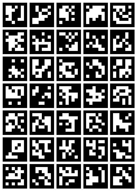
  • boardImage: the output image with the board.
  • The third parameter is the (optional) margin in pixels, so none of the markers are touching the image border. In this case the margin is 10.
  • Finally, the size of the marker border, similarly to generateImageMarker() function. The default value is 1.

A full working example of board creation is included in the samples/cpp/tutorial_code/objectDetection/create_board.cpp

The output image will be something like this:

The samples now take input via commandline via the cv::CommandLineParser. For this file the example parameters will look like:

"_output_path_/aboard.png" -w=5 -h=7 -l=100 -s=10 -d=10

Refine marker detection

ArUco boards can also be used to improve the detection of markers. If we have detected a subset of the markers that belongs to the board, we can use these markers and the board layout information to try to find the markers that have not been previously detected.

This can be done using the cv::aruco::refineDetectedMarkers() function, which should be called after calling cv::aruco::ArucoDetector::detectMarkers().

The main parameters of this function are the original image where markers were detected, the board object, the detected marker corners, the detected marker ids and the rejected marker corners.

The rejected corners can be obtained from the cv::aruco::ArucoDetector::detectMarkers() function and are also known as marker candidates. This candidates are square shapes that have been found in the original image but have failed to pass the identification step (i.e. their inner codification presents too many errors) and thus they have not been recognized as markers.

However, these candidates are sometimes actual markers that have not been correctly identified due to high noise in the image, very low resolution or other related problems that affect to the binary code extraction. The cv::aruco::ArucoDetector::refineDetectedMarkers() function finds correspondences between these candidates and the missing markers of the board. This search is based on two parameters:

  • Distance between the candidate and the projection of the missing marker. To obtain these projections, it is necessary to have detected at least one marker of the board. The projections are obtained using the camera parameters (camera matrix and distortion coefficients) if they are provided. If not, the projections are obtained from local homography and only planar board are allowed (i.e. the Z coordinate of all the marker corners should be the same). The minRepDistance parameter in refineDetectedMarkers() determines the minimum euclidean distance between the candidate corners and the projected marker corners (default value 10).
  • Binary codification. If a candidate surpasses the minimum distance condition, its internal bits are analyzed again to determine if it is actually the projected marker or not. However, in this case, the condition is not so strong and the number of allowed erroneous bits can be higher. This is indicated in the errorCorrectionRate parameter (default value 3.0). If a negative value is provided, the internal bits are not analyzed at all and only the corner distances are evaluated.

This is an example of using the cv::aruco::ArucoDetector::refineDetectedMarkers() function:

// Detect markers
detector.detectMarkers(image, corners, ids, rejected);
// Refind strategy to detect more markers
if(refindStrategy)
detector.refineDetectedMarkers(image, board, corners, ids, rejected, camMatrix,
distCoeffs);

It must also be noted that, in some cases, if the number of detected markers in the first place is too low (for instance only 1 or 2 markers), the projections of the missing markers can be of bad quality, producing erroneous correspondences.

See module samples for a more detailed implementation.