

Stereo Correspondence#
Detailed Description#
Namespaces#
Classes#
Name |
Description |
|---|---|
|
Class for computing stereo correspondence using the block matching algorithm, introduced and contributed to OpenCV by K. Konolige. View details |
|
The base class for stereo correspondence algorithms. View details |
|
The class implements the modified H. Hirschmuller algorithm [141] that differs from the original one as follows: View details |
Enumerations#
enum cv::StereoMatcher {
    cv::DISP_SHIFT = 4,
    cv::DISP_SCALE = (1 << DISP_SHIFT)
}
enum cv::StereoBM {
    cv::PREFILTER_NORMALIZED_RESPONSE = 0,
    cv::PREFILTER_XSOBEL = 1
}
enum cv::StereoSGBM {
    cv::MODE_SGBM = 0,
    cv::MODE_HH = 1,
    cv::MODE_SGBM_3WAY = 2,
    cv::MODE_HH4 = 3
}Functions#
Return |
Name |
Description |
|---|---|---|
|
|
Computes disparity map for the specified stereo pair. |
|
Creates StereoBM object. |
|
|
|
Creates StereoSGBM object. |
|
|
Filters off small noise blobs (speckles) in the disparity map. |
|
||
|
||
|
||
|
||
|
||
|
||
|
||
|
||
|
||
|
||
|
||
|
||
|
||
|
||
|
||
|
||
|
||
|
computes valid disparity ROI from the valid ROIs of the rectified images (that are returned by stereoRectify) |
|
|
|
|
|
|
Reprojects a disparity image to 3D space. |
|
|
|
|
|
|
|
|
|
|
|
|
|
|
|
|
|
|
|
|
|
|
|
|
|
|
|
|
|
|
|
|
|
|
|
|
|
|
|
|
|
|
|
|
|
|
|
|
|
|
|
|
|
|
|
|
|
|
|
Stereo rectification for fisheye camera model. |
|
|
Computes rectification transforms for each head of a calibrated stereo camera. |
|
|
Computes a rectification transform for an uncalibrated stereo camera. |
|
|
validates disparity using the left-right check. The matrix “cost” should be computed by the stereo correspondence algorithm |
Enumeration Type Documentation#
enum#
#include <opencv2/stereo.hpp>
Enumerator:
|
|
enum#
#include <opencv2/stereo.hpp>
Enumerator:
|
|
enum#
#include <opencv2/stereo.hpp>
Enumerator:
|
|
|
|
Function Documentation#
filterSpeckles()#
void cv::filterSpeckles(
InputOutputArray img,
double newVal,
int maxSpeckleSize,
double maxDiff,
InputOutputArray buf = noArray() )
#include <opencv2/stereo.hpp>
Python:
cv.filterSpeckles(img, newVal, maxSpeckleSize, maxDiff[, buf]) -> img, buf
Filters off small noise blobs (speckles) in the disparity map.
Parameters
img— The input 16-bit signed disparity imagenewVal— The disparity value used to paint-off the specklesmaxSpeckleSize— The maximum speckle size to consider it a speckle. Larger blobs are not affected by the algorithmmaxDiff— Maximum difference between neighbor disparity pixels to put them into the same blob. Note that since StereoBM, StereoSGBM and may be other algorithms return a fixed-point disparity map, where disparity values are multiplied by 16, this scale factor should be taken into account when specifying this parameter value.buf— The optional temporary buffer to avoid memory allocation within the function.
getValidDisparityROI()#
Rect cv::getValidDisparityROI(
Rect roi1,
Rect roi2,
int minDisparity,
int numberOfDisparities,
int blockSize )
#include <opencv2/stereo.hpp>
Python:
cv.getValidDisparityROI(roi1, roi2, minDisparity, numberOfDisparities, blockSize) -> retval
computes valid disparity ROI from the valid ROIs of the rectified images (that are returned by stereoRectify)
rectify3Collinear()#
float cv::rectify3Collinear(
InputArray _cameraMatrix1,
InputArray _distCoeffs1,
InputArray _cameraMatrix2,
InputArray _distCoeffs2,
InputArray _cameraMatrix3,
InputArray _distCoeffs3,
InputArrayOfArrays _imgpt1,
InputArrayOfArrays _imgpt3,
Size imageSize,
InputArray _Rmat12,
InputArray _Tmat12,
InputArray _Rmat13,
InputArray _Tmat13,
OutputArray _Rmat1,
OutputArray _Rmat2,
OutputArray _Rmat3,
OutputArray _Pmat1,
OutputArray _Pmat2,
OutputArray _Pmat3,
OutputArray _Qmat,
double alpha,
Size newImgSize,
Rect * roi1,
Rect * roi2,
int flags )
#include <opencv2/stereo.hpp>
reprojectImageTo3D()#
void cv::reprojectImageTo3D(
InputArray disparity,
OutputArray _3dImage,
InputArray Q,
bool handleMissingValues = false,
int ddepth = -1 )
#include <opencv2/stereo.hpp>
Python:
cv.reprojectImageTo3D(disparity, Q[, _3dImage[, handleMissingValues[, ddepth]]]) -> _3dImage
Reprojects a disparity image to 3D space.
The function transforms a single-channel disparity map to a 3-channel image representing a 3D surface. That is, for each pixel (x,y) and the corresponding disparity d=disparity(x,y) , it computes:
See also
To reproject a sparse set of points {(x,y,d),…} to 3D space, use perspectiveTransform.
Parameters
disparity— Input single-channel 8-bit unsigned, 16-bit signed, 32-bit signed or 32-bit floating-point disparity image. The values of 8-bit / 16-bit signed formats are assumed to have no fractional bits. If the disparity is 16-bit signed format, as computed by StereoBM or StereoSGBM and maybe other algorithms, it should be divided by 16 (and scaled to float) before being used here._3dImage— Output 3-channel floating-point image of the same size as disparity. Each element of _3dImage(x,y) contains 3D coordinates of the point (x,y) computed from the disparity map. If one uses Q obtained by stereoRectify, then the returned points are represented in the first camera’s rectified coordinate system.Q— \(4 \times 4\) perspective transformation matrix that can be obtained with stereoRectify.handleMissingValues— Indicates, whether the function should handle missing values (i.e. points where the disparity was not computed). If handleMissingValues=true, then pixels with the minimal disparity that corresponds to the outliers (see StereoMatcher::compute ) are transformed to 3D points with a very large Z value (currently set to 10000).ddepth— The optional output array depth. If it is -1, the output image will have CV_32F depth. ddepth can also be set to CV_16S, CV_32S or CV_32F.
stereoRectify()#
void cv::fisheye::stereoRectify(
InputArray K1,
InputArray D1,
InputArray K2,
InputArray D2,
const Size & imageSize,
InputArray R,
InputArray tvec,
OutputArray R1,
OutputArray R2,
OutputArray P1,
OutputArray P2,
OutputArray Q,
int flags,
const Size & newImageSize = Size(),
double balance = 0.0,
double fov_scale = 1.0 )
#include <opencv2/stereo.hpp>
Python:
cv.fisheye.stereoRectify(K1, D1, K2, D2, imageSize, R, tvec, flags[, R1[, R2[, P1[, P2[, Q[, newImageSize[, balance[, fov_scale]]]]]]]]) -> R1, R2, P1, P2, Q
Stereo rectification for fisheye camera model.
Parameters
K1— First camera intrinsic matrix.D1— First camera distortion parameters.K2— Second camera intrinsic matrix.D2— Second camera distortion parameters.imageSize— Size of the image used for stereo calibration.R— Rotation matrix between the coordinate systems of the first and the second cameras.tvec— Translation vector between coordinate systems of the cameras.R1— Output 3x3 rectification transform (rotation matrix) for the first camera.R2— Output 3x3 rectification transform (rotation matrix) for the second camera.P1— Output 3x4 projection matrix in the new (rectified) coordinate systems for the first camera.P2— Output 3x4 projection matrix in the new (rectified) coordinate systems for the second camera.Q— Output \(4 \times 4\) disparity-to-depth mapping matrix (see reprojectImageTo3D ).flags— Operation flags that may be zero or cv::CALIB_ZERO_DISPARITY . If the flag is set, the function makes the principal points of each camera have the same pixel coordinates in the rectified views. And if the flag is not set, the function may still shift the images in the horizontal or vertical direction (depending on the orientation of epipolar lines) to maximize the useful image area.newImageSize— New image resolution after rectification. The same size should be passed to initUndistortRectifyMap (see the stereo_calib.cpp sample in OpenCV samples directory). When (0,0) is passed (default), it is set to the original imageSize . Setting it to larger value can help you preserve details in the original image, especially when there is a big radial distortion.balance— Sets the new focal length in range between the min focal length and the max focal length. Balance is in range of [0, 1].fov_scale— Divisor for new focal length.
stereoRectify()#
void cv::stereoRectify(
InputArray cameraMatrix1,
InputArray distCoeffs1,
InputArray cameraMatrix2,
InputArray distCoeffs2,
Size imageSize,
InputArray R,
InputArray T,
OutputArray R1,
OutputArray R2,
OutputArray P1,
OutputArray P2,
OutputArray Q,
int flags = STEREO_ZERO_DISPARITY,
double alpha = -1,
Size newImageSize = Size(),
Rect * validPixROI1 = 0,
Rect * validPixROI2 = 0 )
#include <opencv2/stereo.hpp>
Python:
cv.stereoRectify(cameraMatrix1, distCoeffs1, cameraMatrix2, distCoeffs2, imageSize, R, T[, R1[, R2[, P1[, P2[, Q[, flags[, alpha[, newImageSize]]]]]]]]) -> R1, R2, P1, P2, Q, validPixROI1, validPixROI2
Computes rectification transforms for each head of a calibrated stereo camera.
The function computes the rotation matrices for each camera that (virtually) make both camera image planes the same plane. Consequently, this makes all the epipolar lines parallel and thus simplifies the dense stereo correspondence problem. The function takes the matrices computed by stereoCalibrate as input. As output, it provides two rotation matrices and also two projection matrices in the new coordinates. The function distinguishes the following two cases:
Horizontal stereo: the first and the second camera views are shifted relative to each other mainly along the x-axis (with possible small vertical shift). In the rectified images, the corresponding epipolar lines in the left and right cameras are horizontal and have the same y-coordinate. P1 and P2 look like: $\( \texttt{P1} = \begin{bmatrix} f & 0 & cx_1 & 0 \\ 0 & f & cy & 0 \\ 0 & 0 & 1 & 0 \end{bmatrix} \)\( \)\( \texttt{P2} = \begin{bmatrix} f & 0 & cx_2 & T_x \cdot f \\ 0 & f & cy & 0 \\ 0 & 0 & 1 & 0 \end{bmatrix} , \)\( \)\( \texttt{Q} = \begin{bmatrix} 1 & 0 & 0 & -cx_1 \\ 0 & 1 & 0 & -cy \\ 0 & 0 & 0 & f \\ 0 & 0 & -\frac{1}{T_x} & \frac{cx_1 - cx_2}{T_x} \end{bmatrix} \)\( where \)T_x\( is a horizontal shift between the cameras and \)cx_1=cx_2$ if STEREO_ZERO_DISPARITY is set.
Vertical stereo: the first and the second camera views are shifted relative to each other mainly in the vertical direction (and probably a bit in the horizontal direction too). The epipolar lines in the rectified images are vertical and have the same x-coordinate. P1 and P2 look like: $\( \texttt{P1} = \begin{bmatrix} f & 0 & cx & 0 \\ 0 & f & cy_1 & 0 \\ 0 & 0 & 1 & 0 \end{bmatrix} \)\( \)\( \texttt{P2} = \begin{bmatrix} f & 0 & cx & 0 \\ 0 & f & cy_2 & T_y \cdot f \\ 0 & 0 & 1 & 0 \end{bmatrix}, \)\( \)\( \texttt{Q} = \begin{bmatrix} 1 & 0 & 0 & -cx \\ 0 & 1 & 0 & -cy_1 \\ 0 & 0 & 0 & f \\ 0 & 0 & -\frac{1}{T_y} & \frac{cy_1 - cy_2}{T_y} \end{bmatrix} \)\( where \)T_y\( is a vertical shift between the cameras and \)cy_1=cy_2$ if STEREO_ZERO_DISPARITY is set.
As you can see, the first three columns of P1 and P2 will effectively be the new “rectified” camera matrices. The matrices, together with R1 and R2 , can then be passed to initUndistortRectifyMap to initialize the rectification map for each camera.
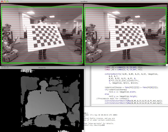
See below the screenshot from the stereo_calib.cpp sample. Some red horizontal lines pass through the corresponding image regions. This means that the images are well rectified, which is what most stereo correspondence algorithms rely on. The green rectangles are roi1 and roi2 . You see that their interiors are all valid pixels.
Parameters
cameraMatrix1— First camera intrinsic matrix.distCoeffs1— First camera distortion parameters.cameraMatrix2— Second camera intrinsic matrix.distCoeffs2— Second camera distortion parameters.imageSize— Size of the image used for stereo calibration.R— Rotation matrix from the coordinate system of the first camera to the second camera, see stereoCalibrate.T— Translation vector from the coordinate system of the first camera to the second camera, see stereoCalibrate.R1— Output 3x3 rectification transform (rotation matrix) for the first camera. This matrix brings points given in the unrectified first camera’s coordinate system to points in the rectified first camera’s coordinate system. In more technical terms, it performs a change of basis from the unrectified first camera’s coordinate system to the rectified first camera’s coordinate system.R2— Output 3x3 rectification transform (rotation matrix) for the second camera. This matrix brings points given in the unrectified second camera’s coordinate system to points in the rectified second camera’s coordinate system. In more technical terms, it performs a change of basis from the unrectified second camera’s coordinate system to the rectified second camera’s coordinate system.P1— Output 3x4 projection matrix in the new (rectified) coordinate systems for the first camera, i.e. it projects points given in the rectified first camera coordinate system into the rectified first camera’s image.P2— Output 3x4 projection matrix in the new (rectified) coordinate systems for the second camera, i.e. it projects points given in the rectified first camera coordinate system into the rectified second camera’s image.Q— Output \(4 \times 4\) disparity-to-depth mapping matrix (see reprojectImageTo3D).flags— Operation flags that may be zero or STEREO_ZERO_DISPARITY . If the flag is set, the function makes the principal points of each camera have the same pixel coordinates in the rectified views. And if the flag is not set, the function may still shift the images in the horizontal or vertical direction (depending on the orientation of epipolar lines) to maximize the useful image area.alpha— Free scaling parameter. If it is -1 or absent, the function performs the default scaling. Otherwise, the parameter should be between 0 and 1. alpha=0 means that the rectified images are zoomed and shifted so that only valid pixels are visible (no black areas after rectification). alpha=1 means that the rectified image is decimated and shifted so that all the pixels from the original images from the cameras are retained in the rectified images (no source image pixels are lost). Any intermediate value yields an intermediate result between those two extreme cases.newImageSize— New image resolution after rectification. The same size should be passed to initUndistortRectifyMap (see the stereo_calib.cpp sample in OpenCV samples directory). When (0,0) is passed (default), it is set to the original imageSize . Setting it to a larger value can help you preserve details in the original image, especially when there is a big radial distortion.validPixROI1— Optional output rectangles inside the rectified images where all the pixels are valid. If alpha=0 , the ROIs cover the whole images. Otherwise, they are likely to be smaller (see the picture below).validPixROI2— Optional output rectangles inside the rectified images where all the pixels are valid. If alpha=0 , the ROIs cover the whole images. Otherwise, they are likely to be smaller (see the picture below).
stereoRectifyUncalibrated()#
bool cv::stereoRectifyUncalibrated(
InputArray points1,
InputArray points2,
InputArray F,
Size imgSize,
OutputArray H1,
OutputArray H2,
double threshold = 5 )
#include <opencv2/stereo.hpp>
Python:
cv.stereoRectifyUncalibrated(points1, points2, F, imgSize[, H1[, H2[, threshold]]]) -> retval, H1, H2
Computes a rectification transform for an uncalibrated stereo camera.
The function computes the rectification transformations without knowing intrinsic parameters of the cameras and their relative position in the space, which explains the suffix “uncalibrated”. Another related difference from stereoRectify is that the function outputs not the rectification transformations in the object (3D) space, but the planar perspective transformations encoded by the homography matrices H1 and H2 . The function implements the algorithm [132] .
Note
While the algorithm does not need to know the intrinsic parameters of the cameras, it heavily depends on the epipolar geometry. Therefore, if the camera lenses have a significant distortion, it would be better to correct it before computing the fundamental matrix and calling this function. For example, distortion coefficients can be estimated for each head of stereo camera separately by using calibrateCamera . Then, the images can be corrected using undistort , or just the point coordinates can be corrected with undistortPoints .
Parameters
points1— Array of feature points in the first image.points2— The corresponding points in the second image. The same formats as in findFundamentalMat are supported.F— Input fundamental matrix. It can be computed from the same set of point pairs using findFundamentalMat .imgSize— Size of the image.H1— Output rectification homography matrix for the first image.H2— Output rectification homography matrix for the second image.threshold— Optional threshold used to filter out the outliers. If the parameter is greater than zero, all the point pairs that do not comply with the epipolar geometry (that is, the points for which \(|\texttt{points2[i]}^T \cdot \texttt{F} \cdot \texttt{points1[i]}|>\texttt{threshold}\) ) are rejected prior to computing the homographies. Otherwise, all the points are considered inliers.
validateDisparity()#
void cv::validateDisparity(
InputOutputArray disparity,
InputArray cost,
int minDisparity,
int numberOfDisparities,
int disp12MaxDisp = 1 )
#include <opencv2/stereo.hpp>
Python:
cv.validateDisparity(disparity, cost, minDisparity, numberOfDisparities[, disp12MaxDisp]) -> disparity
validates disparity using the left-right check. The matrix “cost” should be computed by the stereo correspondence algorithm