

Camera Calibration#
Topics#
Detailed Description#
The functions in this section use a so-called pinhole camera model. The view of a scene is obtained by projecting a scene’s 3D point \(P_w\) into the image plane using a perspective transformation which forms the corresponding pixel \(p\). Both \(P_w\) and \(p\) are represented in homogeneous coordinates, i.e. as 3D and 2D homogeneous vector respectively. You will find a brief introduction to projective geometry, homogeneous vectors and homogeneous transformations at the end of this section’s introduction. For more succinct notation, we often drop the ‘homogeneous’ and say vector instead of homogeneous vector.
The distortion-free projective transformation given by a pinhole camera model is shown below.
where \(P_w\) is a 3D point expressed with respect to the world coordinate system, \(p\) is a 2D pixel in the image plane, \(A\) is the camera intrinsic matrix, \(R\) and \(t\) are the rotation and translation that describe the change of coordinates from world to camera coordinate systems (or camera frame) and \(s\) is the projective transformation’s arbitrary scaling and not part of the camera model.
The camera intrinsic matrix \(A\) (notation used as in [353] and also generally notated as \(K\)) projects 3D points given in the camera coordinate system to 2D pixel coordinates, i.e.
The camera intrinsic matrix \(A\) is composed of the focal lengths \(f_x\) and \(f_y\), which are expressed in pixel units, and the principal point \((c_x, c_y)\), that is usually close to the image center:
and thus
The matrix of intrinsic parameters does not depend on the scene viewed. So, once estimated, it can be re-used as long as the focal length is fixed (in case of a zoom lens). Thus, if an image from the camera is scaled by a factor, all of these parameters need to be scaled (multiplied/divided, respectively) by the same factor.
The joint rotation-translation matrix \([R|t]\) is the matrix product of a projective transformation and a homogeneous transformation. The 3-by-4 projective transformation maps 3D points represented in camera coordinates to 2D points in the image plane and represented in normalized camera coordinates \(x' = X_c / Z_c\) and \(y' = Y_c / Z_c\):
The homogeneous transformation is encoded by the extrinsic parameters \(R\) and \(t\) and represents the change of basis from world coordinate system \(w\) to the camera coordinate sytem \(c\). Thus, given the representation of the point \(P\) in world coordinates, \(P_w\), we obtain \(P\)’s representation in the camera coordinate system, \(P_c\), by
This homogeneous transformation is composed out of \(R\), a 3-by-3 rotation matrix, and \(t\), a 3-by-1 translation vector:
and therefore
Combining the projective transformation and the homogeneous transformation, we obtain the projective transformation that maps 3D points in world coordinates into 2D points in the image plane and in normalized camera coordinates:
with \(x' = X_c / Z_c\) and \(y' = Y_c / Z_c\). Putting the equations for instrincs and extrinsics together, we can write out \(s \; p = A \begin{bmatrix} R|t \end{bmatrix} P_w\) as
If \(Z_c \ne 0\), the transformation above is equivalent to the following,
with
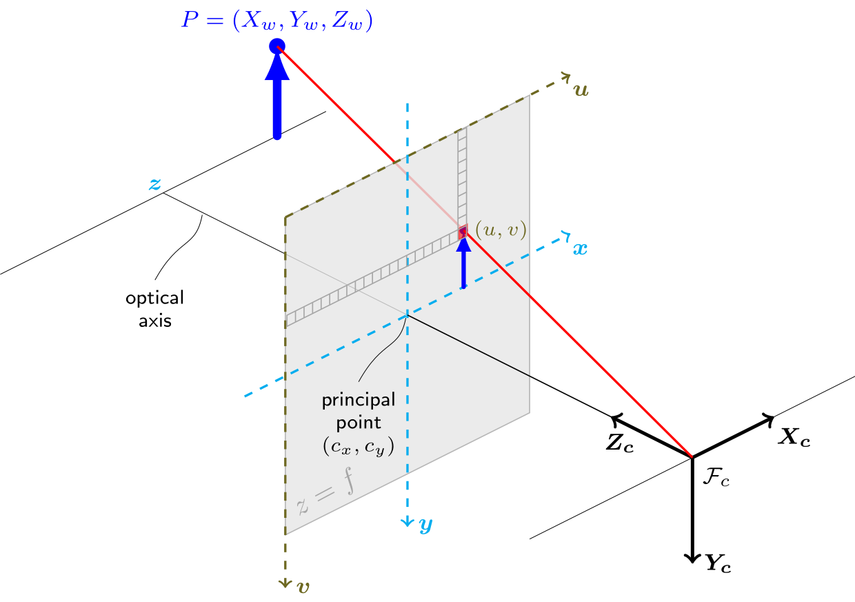
The following figure illustrates the pinhole camera model.
Real lenses usually have some distortion, mostly radial distortion, and slight tangential distortion. So, the above model is extended as:
where
with
and
if \(Z_c \ne 0\).
The distortion parameters are the radial coefficients \(k_1\), \(k_2\), \(k_3\), \(k_4\), \(k_5\), and \(k_6\) , \(p_1\) and \(p_2\) are the tangential distortion coefficients, and \(s_1\), \(s_2\), \(s_3\), and \(s_4\), are the thin prism distortion coefficients. Higher-order coefficients are not considered in OpenCV.
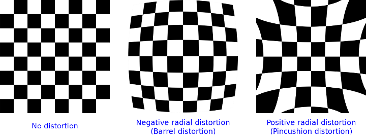
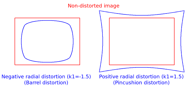
The next figures show two common types of radial distortion: barrel distortion ( \( 1 + k_1 r^2 + k_2 r^4 + k_3 r^6 \) monotonically decreasing) and pincushion distortion ( \( 1 + k_1 r^2 + k_2 r^4 + k_3 r^6 \) monotonically increasing). Radial distortion is always monotonic for real lenses, and if the estimator produces a non-monotonic result, this should be considered a calibration failure. More generally, radial distortion must be monotonic and the distortion function must be bijective. A failed estimation result may look deceptively good near the image center but will work poorly in e.g. AR/SFM applications. The optimization method used in OpenCV camera calibration does not include these constraints as the framework does not support the required integer programming and polynomial inequalities. See issue #15992 for additional information.
In some cases, the image sensor may be tilted in order to focus an oblique plane in front of the camera (Scheimpflug principle). This can be useful for particle image velocimetry (PIV) or triangulation with a laser fan. The tilt causes a perspective distortion of \(x''\) and \(y''\). This distortion can be modeled in the following way, see e.g. [191].
where
and the matrix \(R(\tau_x, \tau_y)\) is defined by two rotations with angular parameter \(\tau_x\) and \(\tau_y\), respectively,
In the functions below the coefficients are passed or returned as
vector. That is, if the vector contains four elements, it means that \(k_3=0\) . The distortion coefficients do not depend on the scene viewed. Thus, they also belong to the intrinsic camera parameters. And they remain the same regardless of the captured image resolution. If, for example, a camera has been calibrated on images of 320 x 240 resolution, absolutely the same distortion coefficients can be used for 640 x 480 images from the same camera while \(f_x\), \(f_y\), \(c_x\), and \(c_y\) need to be scaled appropriately.
The functions below use the above model to do the following:
Project 3D points to the image plane given intrinsic and extrinsic parameters.
Compute extrinsic parameters given intrinsic parameters, a few 3D points, and their projections.
Estimate intrinsic and extrinsic camera parameters from several views of a known calibration pattern (every view is described by several 3D-2D point correspondences).
Estimate the relative position and orientation of the stereo camera “heads” and compute the rectification* transformation that makes the camera optical axes parallel.
Homogeneous Coordinates
Homogeneous Coordinates are a system of coordinates that are used in projective geometry. Their use allows to represent points at infinity by finite coordinates and simplifies formulas when compared to the cartesian counterparts, e.g. they have the advantage that affine transformations can be expressed as linear homogeneous transformation.
One obtains the homogeneous vector \(P_h\) by appending a 1 along an n-dimensional cartesian vector \(P\) e.g. for a 3D cartesian vector the mapping \(P \rightarrow P_h\) is:
For the inverse mapping \(P_h \rightarrow P\), one divides all elements of the homogeneous vector by its last element, e.g. for a 3D homogeneous vector one gets its 2D cartesian counterpart by:
if \(W \ne 0\).
Due to this mapping, all multiples \(k P_h\), for \(k \ne 0\), of a homogeneous point represent the same point \(P_h\). An intuitive understanding of this property is that under a projective transformation, all multiples of \(P_h\) are mapped to the same point. This is the physical observation one does for pinhole cameras, as all points along a ray through the camera’s pinhole are projected to the same image point, e.g. all points along the red ray in the image of the pinhole camera model above would be mapped to the same image coordinate. This property is also the source for the scale ambiguity s in the equation of the pinhole camera model.
As mentioned, by using homogeneous coordinates we can express any change of basis parameterized by \(R\) and \(t\) as a linear transformation, e.g. for the change of basis from coordinate system 0 to coordinate system 1 becomes:
Homogeneous Transformations, Object frame / Camera frame
Change of basis or computing the 3D coordinates from one frame to another frame can be achieved easily using the following notation:
For a 3D points ( \( \mathbf{X}_o \)) expressed in the object frame, the homogeneous transformation matrix \( {}^{c}\mathbf{T}_o \) allows computing the corresponding coordinate ( \( \mathbf{X}_c \)) in the camera frame. This transformation matrix is composed of a 3x3 rotation matrix \( {}^{c}\mathbf{R}_o \) and a 3x1 translation vector \( {}^{c}\mathbf{t}_o \). The 3x1 translation vector \( {}^{c}\mathbf{t}_o \) is the position of the object frame in the camera frame and the 3x3 rotation matrix \( {}^{c}\mathbf{R}_o \) the orientation of the object frame in the camera frame. With this simple notation, it is easy to chain the transformations. For instance, to compute the 3D coordinates of a point expressed in the object frame in the world frame can be done with:
Similarly, computing the inverse transformation can be done with:
The inverse of an homogeneous transformation matrix is then:
One can note that the inverse of a 3x3 rotation matrix is directly its matrix transpose. This figure summarizes the whole process. The object pose returned for instance by the solvePnP function or pose from fiducial marker detection is this \( {}^{c}\mathbf{T}_o \) transformation. The camera intrinsic matrix \( \mathbf{K} \) allows projecting the 3D point expressed in the camera frame onto the image plane assuming a perspective projection model (pinhole camera model). Image coordinates extracted from classical image processing functions assume a (u,v) top-left coordinates frame.
Note
for an online video course on this topic, see for instance:
the 3x3 rotation matrix is composed of 9 values but describes a 3 dof transformation
some additional properties of the 3x3 rotation matrix are:
\( \mathrm{det} \left( \mathbf{R} \right) = 1 \)
\( \mathbf{R} \mathbf{R}^{\top} = \mathbf{R}^{\top} \mathbf{R} = \mathrm{I}_{3 \times 3} \)
interpolating rotation can be done using the Slerp (spherical linear interpolation) method
quick conversions between the different rotation formalisms can be done using this online tool Intrinsic parameters from camera lens specifications
When dealing with industrial cameras, the camera intrinsic matrix or more precisely \( \left(f_x, f_y \right) \) can be deduced, approximated from the camera specifications:
In a same way, the physical focal length can be deduced from the angular field of view:
This latter conversion can be useful when using a rendering software to mimic a physical camera device.
See also calibrationMatrixValues
Additional references, notes
Note
Many functions in this module take a camera intrinsic matrix as an input parameter. Although all functions assume the same structure of this parameter, they may name it differently. The parameter’s description, however, will be clear in that a camera intrinsic matrix with the structure shown above is required.
A calibration sample for 3 cameras in a horizontal position can be found at opencv_source_code/samples/cpp/3calibration.cpp
A calibration sample based on a sequence of images can be found at opencv_source_code/samples/cpp/calibration.cpp
A calibration sample in order to do 3D reconstruction can be found at opencv_source_code/samples/cpp/build3dmodel.cpp
A calibration example on stereo calibration can be found at opencv_source_code/samples/cpp/stereo_calib.cpp
A calibration example on stereo matching can be found at opencv_source_code/samples/cpp/stereo_match.cpp
(Python) A camera calibration sample can be found at opencv_source_code/samples/python/calibrate.py
Namespaces#
Enumerations#
enum cv {
    CALIB_USE_INTRINSIC_GUESS = 0x00001,
    CALIB_FIX_ASPECT_RATIO = 0x00002,
    CALIB_FIX_PRINCIPAL_POINT = 0x00004,
    CALIB_ZERO_TANGENT_DIST = 0x00008,
    CALIB_FIX_FOCAL_LENGTH = 0x00010,
    CALIB_FIX_K1 = 0x00020,
    CALIB_FIX_K2 = 0x00040,
    CALIB_FIX_K3 = 0x00080,
    CALIB_FIX_K4 = 0x00800,
    CALIB_FIX_K5 = 0x01000,
    CALIB_FIX_K6 = 0x02000,
    CALIB_RATIONAL_MODEL = 0x04000,
    CALIB_THIN_PRISM_MODEL = 0x08000,
    CALIB_FIX_S1_S2_S3_S4 = 0x10000,
    CALIB_TILTED_MODEL = 0x40000,
    CALIB_FIX_TAUX_TAUY = 0x80000,
    CALIB_USE_QR = 0x100000,
    CALIB_FIX_TANGENT_DIST = 0x200000,
    CALIB_FIX_INTRINSIC = 0x00100,
    CALIB_SAME_FOCAL_LENGTH = 0x00200,
    CALIB_ZERO_DISPARITY = 0x00400,
    CALIB_USE_LU = (1 << 17),
    CALIB_DISABLE_SCHUR_COMPLEMENT = (1 << 18),
    CALIB_USE_EXTRINSIC_GUESS = (1 << 22),
    CALIB_RECOMPUTE_EXTRINSIC = (1 << 23),
    CALIB_CHECK_COND = (1 << 24),
    CALIB_FIX_SKEW = (1 << 25),
    CALIB_STEREO_REGISTRATION = (1 << 26)
}
enum cv::CameraModel {
    cv::CALIB_MODEL_PINHOLE = 0,
    cv::CALIB_MODEL_FISHEYE = 1
}Enumeration Type Documentation#
enum#
#include <opencv2/calib.hpp>
Enumerator:
|
Use user provided intrinsics as initial point for optimization. |
|
Use with CALIB_USE_INTRINSIC_GUESS. The ratio fx/fy stays the same as in the input cameraMatrix. |
|
The principal point (cx, cy) stays the same as in the input camera matrix. Image center is used as principal point, if CALIB_USE_INTRINSIC_GUESS is not set. |
|
For pinhole model only. Tangential distortion coefficients \((p_1, p_2)\) are set to zeros and stay zero. |
|
Use with CALIB_USE_INTRINSIC_GUESS. The focal length (fx, fy) stays the same as in the input cameraMatrix. |
|
The corresponding distortion coefficient is not changed during the optimization. 0 value is used, if CALIB_USE_INTRINSIC_GUESS is not set. |
|
The corresponding distortion coefficient is not changed during the optimization. 0 value is used, if CALIB_USE_INTRINSIC_GUESS is not set. |
|
The corresponding distortion coefficient is not changed during the optimization. 0 value is used, if CALIB_USE_INTRINSIC_GUESS is not set. |
|
The corresponding distortion coefficient is not changed during the optimization. 0 value is used, if CALIB_USE_INTRINSIC_GUESS is not set. |
|
For pinhole model only. The corresponding distortion coefficient is not changed during the optimization. 0 value is used, if CALIB_USE_INTRINSIC_GUESS is not set. |
|
For pinhole model only. The corresponding distortion coefficient is not changed during the optimization. 0 value is used, if CALIB_USE_INTRINSIC_GUESS is not set. |
|
For pinhole model only. Use rational distortion model with coefficients k4..k6. |
|
For pinhole model only. Use thin prism distortion model with coefficients s1..s4. |
|
For pinhole model only. The thin prism distortion coefficients are not changed during the optimization. 0 value is used, if CALIB_USE_INTRINSIC_GUESS is not set. |
|
For pinhole model only. Coefficients tauX and tauY are enabled in camera matrix. |
|
For pinhole model only. The tauX and tauY coefficients are not changed during the optimization. 0 value is used, if CALIB_USE_INTRINSIC_GUESS is not set. |
|
Use QR instead of SVD decomposition for solving. Faster but potentially less precise. |
|
For pinhole model only. Tangential distortion coefficients (p1,p2) are set to zeros and stay zero. |
|
For stereo and milti-camera calibration only. Do not optimize cameras intrinsics. |
|
For stereo calibration only. Use the same focal length for cameras in pair. |
|
Deprecated synonim of STEREO_ZERO_DISPARITY. See stereoRectify. |
|
use LU instead of SVD decomposition for solving. much faster but potentially less precise |
|
disable Schur complement (use Bouguet calibration engine) |
|
For stereo and multi-view calibration. Use user provided extrinsics (R, T) as initial point for optimization. |
|
For fisheye model only. Recompute board position on each calibration iteration. |
|
For fisheye model only. Check SVD decomposition quality for each frame during extrinsics estimation. |
|
For fisheye model only. Skew coefficient (alpha) is set to zero and stay zero. |
|
For multiview calibration only. Use stereo correspondence approach for initial extrinsics guess. Limitation: all cameras should have the same type. |
CameraModel#
enum cv::CameraModel
#include <opencv2/calib.hpp>
Enumerator:
|
Pinhole camera model. |
|
Fisheye camera model. |
HandEyeCalibrationMethod#
enum cv::HandEyeCalibrationMethod
#include <opencv2/calib.hpp>
Enumerator:
|
A New Technique for Fully Autonomous and Efficient 3D Robotics Hand/Eye Calibration [309]. |
|
Robot Sensor Calibration: Solving AX = XB on the Euclidean Group [237]. |
|
Hand-eye Calibration [143]. |
|
On-line Hand-Eye Calibration [14]. |
|
Hand-Eye Calibration Using Dual Quaternions [73]. |
RobotWorldHandEyeCalibrationMethod#
enum cv::RobotWorldHandEyeCalibrationMethod
#include <opencv2/calib.hpp>
Enumerator:
|
Solving the robot-world/hand-eye calibration problem using the kronecker product [270]. |
|
Simultaneous robot-world and hand-eye calibration using dual-quaternions and kronecker product [180]. |
Function Documentation#
calibrateCamera()#
double cv::calibrateCamera(
InputArrayOfArrays objectPoints,
InputArrayOfArrays imagePoints,
Size imageSize,
InputOutputArray cameraMatrix,
InputOutputArray distCoeffs,
OutputArrayOfArrays rvecs,
OutputArrayOfArrays tvecs,
int flags = 0,
TermCriteria criteria = TermCriteria(TermCriteria::COUNT+TermCriteria::EPS, 500, DBL_EPSILON) )
#include <opencv2/calib.hpp>
Python:
cv.calibrateCamera(objectPoints, imagePoints, imageSize, cameraMatrix, distCoeffs[, rvecs[, tvecs[, flags[, criteria]]]]) -> retval, cameraMatrix, distCoeffs, rvecs, tvecs
cv.calibrateCameraExtended(objectPoints, imagePoints, imageSize, cameraMatrix, distCoeffs[, rvecs[, tvecs[, stdDeviationsIntrinsics[, stdDeviationsExtrinsics[, perViewErrors[, flags[, criteria]]]]]]]) -> retval, cameraMatrix, distCoeffs, rvecs, tvecs, stdDeviationsIntrinsics, stdDeviationsExtrinsics, perViewErrors
This is an overloaded member function, provided for convenience. It differs from the above function only in what argument(s) it accepts.
calibrateCamera()#
double cv::calibrateCamera(
InputArrayOfArrays objectPoints,
InputArrayOfArrays imagePoints,
Size imageSize,
InputOutputArray cameraMatrix,
InputOutputArray distCoeffs,
OutputArrayOfArrays rvecs,
OutputArrayOfArrays tvecs,
OutputArray stdDeviationsIntrinsics,
OutputArray stdDeviationsExtrinsics,
OutputArray perViewErrors,
int flags = 0,
TermCriteria criteria = TermCriteria(TermCriteria::COUNT+TermCriteria::EPS, 500, DBL_EPSILON) )
#include <opencv2/calib.hpp>
Python:
cv.calibrateCamera(objectPoints, imagePoints, imageSize, cameraMatrix, distCoeffs[, rvecs[, tvecs[, flags[, criteria]]]]) -> retval, cameraMatrix, distCoeffs, rvecs, tvecs
cv.calibrateCameraExtended(objectPoints, imagePoints, imageSize, cameraMatrix, distCoeffs[, rvecs[, tvecs[, stdDeviationsIntrinsics[, stdDeviationsExtrinsics[, perViewErrors[, flags[, criteria]]]]]]]) -> retval, cameraMatrix, distCoeffs, rvecs, tvecs, stdDeviationsIntrinsics, stdDeviationsExtrinsics, perViewErrors
Finds the camera intrinsic and extrinsic parameters from several views of a calibration pattern.
The function estimates the intrinsic camera parameters and extrinsic parameters for each of the views. By default, the optimization follows a sparse bundle adjustment formulation with Schur complement; see [308] and [192] for background. Use CALIB_DISABLE_SCHUR_COMPLEMENT to switch to the Bouguet calibration engine. The coordinates of 3D object points and their corresponding 2D projections in each view must be specified. That may be achieved by using an object with known geometry and easily detectable feature points. Such an object is called a calibration rig or calibration pattern, and OpenCV has built-in support for a chessboard as a calibration rig (see findChessboardCorners). Currently, initialization of intrinsic parameters (when CALIB_USE_INTRINSIC_GUESS is not set) is only implemented for planar calibration patterns (where Z-coordinates of the object points must be all zeros). 3D calibration rigs can also be used as long as initial cameraMatrix is provided.
The algorithm performs the following steps:
Compute the initial intrinsic parameters (the option only available for planar calibration patterns) or read them from the input parameters. The distortion coefficients are all set to zeros initially unless some of CALIB_FIX_K? are specified.
Estimate the initial camera pose as if the intrinsic parameters have been already known. This is done using solvePnP .
Run the global Levenberg-Marquardt optimization algorithm to minimize the reprojection error, that is, the total sum of squared distances between the observed feature points imagePoints and the projected (using the current estimates for camera parameters and the poses) object points objectPoints. See projectPoints for details.
In practice, robust acquisition is essential for stable results: use multiple board poses with significant tilt, avoid collecting all views at a single working distance, span the expected working-distance range (a larger board with larger squares can help for longer distances).
Note
If you use a non-square (i.e. non-N-by-N) grid and findChessboardCorners for calibration, and calibrateCamera returns bad values (zero distortion coefficients, \(c_x\) and \(c_y\) very far from the image center, and/or large differences between \(f_x\) and \(f_y\) (ratios of 10:1 or more)), then you are probably using patternSize=cvSize(rows,cols) instead of using patternSize=cvSize(cols,rows) in findChessboardCorners.
The function may throw exceptions, if unsupported combination of parameters is provided or the system is underconstrained.
See also
calibrateCameraRO, findChessboardCorners, solvePnP, initCameraMatrix2D, stereoCalibrate, undistort
Parameters
objectPoints— In the new interface it is a vector of vectors of calibration pattern points in the calibration pattern coordinate space (e.g. std::vector<std::vector<cv::Vec3f>>). The outer vector contains as many elements as the number of pattern views. If the same calibration pattern is shown in each view and it is fully visible, all the vectors will be the same. Although, it is possible to use partially occluded patterns or even different patterns in different views. Then, the vectors will be different. Although the points are 3D, they all lie in the calibration pattern’s XY coordinate plane (thus 0 in the Z-coordinate), if the used calibration pattern is a planar rig. In the old interface all the vectors of object points from different views are concatenated together.imagePoints— In the new interface it is a vector of vectors of the projections of calibration pattern points (e.g. std::vector<std::vector<cv::Vec2f>>). imagePoints.size() and objectPoints.size(), and imagePoints[i].size() and objectPoints[i].size() for each i, must be equal, respectively. In the old interface all the vectors of object points from different views are concatenated together.imageSize— Size of the image used only to initialize the camera intrinsic matrix.cameraMatrix— Input/output 3x3 floating-point camera intrinsic matrix \(\cameramatrix{A}\) . If CALIB_USE_INTRINSIC_GUESS and/or CALIB_FIX_ASPECT_RATIO, CALIB_FIX_PRINCIPAL_POINT or CALIB_FIX_FOCAL_LENGTH are specified, some or all of fx, fy, cx, cy must be initialized before calling the function.distCoeffs— Input/output vector of distortion coefficients \(\distcoeffs\).rvecs— Output vector of rotation vectors (Rodrigues ) estimated for each pattern view (e.g. std::vector<cv::Mat>>). That is, each i-th rotation vector together with the corresponding i-th translation vector (see the next output parameter description) brings the calibration pattern from the object coordinate space (in which object points are specified) to the camera coordinate space. In more technical terms, the tuple of the i-th rotation and translation vector performs a change of basis from object coordinate space to camera coordinate space. Due to its duality, this tuple is equivalent to the position of the calibration pattern with respect to the camera coordinate space.tvecs— Output vector of translation vectors estimated for each pattern view, see parameter description above.stdDeviationsIntrinsics— Output vector of standard deviations estimated for intrinsic parameters. Order of deviations values: \((f_x, f_y, c_x, c_y, k_1, k_2, p_1, p_2, k_3, k_4, k_5, k_6 , s_1, s_2, s_3, s_4, \tau_x, \tau_y)\) If one of parameters is not estimated, it’s deviation is equals to zero.stdDeviationsExtrinsics— Output vector of standard deviations estimated for extrinsic parameters. Order of deviations values: \((R_0, T_0, \dotsc , R_{M - 1}, T_{M - 1})\) where M is the number of pattern views. \(R_i, T_i\) are concatenated 1x3 vectors.perViewErrors— Output vector of the RMS re-projection error estimated for each pattern view.flags— Different flags that may be zero or a combination of the following values:CALIB_USE_INTRINSIC_GUESS cameraMatrix contains valid initial values of fx, fy, cx, cy that are optimized further. Otherwise, (cx, cy) is initially set to the image center ( imageSize is used), and focal distances are computed in a least-squares fashion. Note, that if intrinsic parameters are known, there is no need to use this function just to estimate extrinsic parameters. Use solvePnP instead.
CALIB_DISABLE_SCHUR_COMPLEMENT Disable Schur complement and use the Bouguet calibration engine ([353], [42]).
CALIB_FIX_PRINCIPAL_POINT The principal point is not changed during the global optimization. It stays at the center or at a different location specified when CALIB_USE_INTRINSIC_GUESS is set too.
CALIB_FIX_ASPECT_RATIO The functions consider only fy as a free parameter. The ratio fx/fy stays the same as in the input cameraMatrix . When CALIB_USE_INTRINSIC_GUESS is not set, the actual input values of fx and fy are ignored, only their ratio is computed and used further.
CALIB_ZERO_TANGENT_DIST Tangential distortion coefficients \((p_1, p_2)\) are set to zeros and stay zero.
CALIB_FIX_FOCAL_LENGTH The focal length is not changed during the global optimization if CALIB_USE_INTRINSIC_GUESS is set.
CALIB_FIX_K1,…, CALIB_FIX_K6 The corresponding radial distortion coefficient is not changed during the optimization. If CALIB_USE_INTRINSIC_GUESS is set, the coefficient from the supplied distCoeffs matrix is used. Otherwise, it is set to 0.
CALIB_RATIONAL_MODEL Coefficients k4, k5, and k6 are enabled. To provide the backward compatibility, this extra flag should be explicitly specified to make the calibration function use the rational model and return 8 coefficients or more.
CALIB_THIN_PRISM_MODEL Coefficients s1, s2, s3 and s4 are enabled. To provide the backward compatibility, this extra flag should be explicitly specified to make the calibration function use the thin prism model and return 12 coefficients or more.
CALIB_FIX_S1_S2_S3_S4 The thin prism distortion coefficients are not changed during the optimization. If CALIB_USE_INTRINSIC_GUESS is set, the coefficient from the supplied distCoeffs matrix is used. Otherwise, it is set to 0.
CALIB_TILTED_MODEL Coefficients tauX and tauY are enabled. To provide the backward compatibility, this extra flag should be explicitly specified to make the calibration function use the tilted sensor model and return 14 coefficients.
CALIB_FIX_TAUX_TAUY The coefficients of the tilted sensor model are not changed during the optimization. If CALIB_USE_INTRINSIC_GUESS is set, the coefficient from the supplied distCoeffs matrix is used. Otherwise, it is set to 0.
criteria— Termination criteria for the iterative optimization algorithm.
Returns
the overall RMS re-projection error.
calibrateCameraRO()#
double cv::calibrateCameraRO(
InputArrayOfArrays objectPoints,
InputArrayOfArrays imagePoints,
Size imageSize,
int iFixedPoint,
InputOutputArray cameraMatrix,
InputOutputArray distCoeffs,
OutputArrayOfArrays rvecs,
OutputArrayOfArrays tvecs,
OutputArray newObjPoints,
int flags = 0,
TermCriteria criteria = TermCriteria(TermCriteria::COUNT+TermCriteria::EPS, 500, DBL_EPSILON) )
#include <opencv2/calib.hpp>
Python:
cv.calibrateCameraRO(objectPoints, imagePoints, imageSize, iFixedPoint, cameraMatrix, distCoeffs[, rvecs[, tvecs[, newObjPoints[, flags[, criteria]]]]]) -> retval, cameraMatrix, distCoeffs, rvecs, tvecs, newObjPoints
cv.calibrateCameraROExtended(objectPoints, imagePoints, imageSize, iFixedPoint, cameraMatrix, distCoeffs[, rvecs[, tvecs[, newObjPoints[, stdDeviationsIntrinsics[, stdDeviationsExtrinsics[, stdDeviationsObjPoints[, perViewErrors[, flags[, criteria]]]]]]]]]) -> retval, cameraMatrix, distCoeffs, rvecs, tvecs, newObjPoints, stdDeviationsIntrinsics, stdDeviationsExtrinsics, stdDeviationsObjPoints, perViewErrors
This is an overloaded member function, provided for convenience. It differs from the above function only in what argument(s) it accepts.
calibrateCameraRO()#
double cv::calibrateCameraRO(
InputArrayOfArrays objectPoints,
InputArrayOfArrays imagePoints,
Size imageSize,
int iFixedPoint,
InputOutputArray cameraMatrix,
InputOutputArray distCoeffs,
OutputArrayOfArrays rvecs,
OutputArrayOfArrays tvecs,
OutputArray newObjPoints,
OutputArray stdDeviationsIntrinsics,
OutputArray stdDeviationsExtrinsics,
OutputArray stdDeviationsObjPoints,
OutputArray perViewErrors,
int flags = 0,
TermCriteria criteria = TermCriteria(TermCriteria::COUNT+TermCriteria::EPS, 500, DBL_EPSILON) )
#include <opencv2/calib.hpp>
Python:
cv.calibrateCameraRO(objectPoints, imagePoints, imageSize, iFixedPoint, cameraMatrix, distCoeffs[, rvecs[, tvecs[, newObjPoints[, flags[, criteria]]]]]) -> retval, cameraMatrix, distCoeffs, rvecs, tvecs, newObjPoints
cv.calibrateCameraROExtended(objectPoints, imagePoints, imageSize, iFixedPoint, cameraMatrix, distCoeffs[, rvecs[, tvecs[, newObjPoints[, stdDeviationsIntrinsics[, stdDeviationsExtrinsics[, stdDeviationsObjPoints[, perViewErrors[, flags[, criteria]]]]]]]]]) -> retval, cameraMatrix, distCoeffs, rvecs, tvecs, newObjPoints, stdDeviationsIntrinsics, stdDeviationsExtrinsics, stdDeviationsObjPoints, perViewErrors
Finds the camera intrinsic and extrinsic parameters from several views of a calibration pattern.
This function is an extension of calibrateCamera with the method of releasing object which was proposed in [286]. In many common cases with inaccurate, unmeasured, roughly planar targets (calibration plates), this method can dramatically improve the precision of the estimated camera parameters. Both the object-releasing method and standard method are supported by this function. Use the parameter iFixedPoint for method selection. In the internal implementation, calibrateCamera is a wrapper for this function.
The function estimates the intrinsic camera parameters and extrinsic parameters for each of the views. The object-releasing extension follows [286] and uses the same optimization core as calibrateCamera. See calibrateCamera for other detailed explanations.
See also
calibrateCamera, findChessboardCorners, solvePnP, initCameraMatrix2D, stereoCalibrate, undistort
Parameters
objectPoints— Vector of vectors of calibration pattern points in the calibration pattern coordinate space. See calibrateCamera for details. If the method of releasing object to be used, the identical calibration board must be used in each view and it must be fully visible, and all objectPoints[i] must be the same and all points should be roughly close to a plane. The calibration target has to be rigid, or at least static if the camera (rather than the calibration target) is shifted for grabbing images.imagePoints— Vector of vectors of the projections of calibration pattern points. See calibrateCamera for details.imageSize— Size of the image used only to initialize the intrinsic camera matrix.iFixedPoint— The index of the 3D object point in objectPoints[0] to be fixed. It also acts as a switch for calibration method selection. If object-releasing method to be used, pass in the parameter in the range of [1, objectPoints[0].size()-2], otherwise a value out of this range will make standard calibration method selected. Usually the top-right corner point of the calibration board grid is recommended to be fixed when object-releasing method being utilized. According to [286], two other points are also fixed. In this implementation, objectPoints[0].front and objectPoints[0].back.z are used. With object-releasing method, accurate rvecs, tvecs and newObjPoints are only possible if coordinates of these three fixed points are accurate enough.cameraMatrix— Output 3x3 floating-point camera matrix. See calibrateCamera for details.distCoeffs— Output vector of distortion coefficients. See calibrateCamera for details.rvecs— Output vector of rotation vectors estimated for each pattern view. See calibrateCamera for details.tvecs— Output vector of translation vectors estimated for each pattern view.newObjPoints— The updated output vector of calibration pattern points. The coordinates might be scaled based on three fixed points. The returned coordinates are accurate only if the above mentioned three fixed points are accurate. If not needed, noArray() can be passed in. This parameter is ignored with standard calibration method.stdDeviationsIntrinsics— Output vector of standard deviations estimated for intrinsic parameters. See calibrateCamera for details.stdDeviationsExtrinsics— Output vector of standard deviations estimated for extrinsic parameters. See calibrateCamera for details.stdDeviationsObjPoints— Output vector of standard deviations estimated for refined coordinates of calibration pattern points. It has the same size and order as objectPoints[0] vector. This parameter is ignored with standard calibration method.perViewErrors— Output vector of the RMS re-projection error estimated for each pattern view.flags— Different flags that may be zero or a combination of some predefined values. See calibrateCamera for details. If the method of releasing object is used, the calibration time may be much longer. CALIB_USE_QR or CALIB_USE_LU could be used for faster calibration with potentially less precise and less stable in some rare cases.criteria— Termination criteria for the iterative optimization algorithm.
Returns
the overall RMS re-projection error.
calibrateHandEye()#
void cv::calibrateHandEye(
InputArrayOfArrays R_gripper2base,
InputArrayOfArrays t_gripper2base,
InputArrayOfArrays R_target2cam,
InputArrayOfArrays t_target2cam,
OutputArray R_cam2gripper,
OutputArray t_cam2gripper,
HandEyeCalibrationMethod method = CALIB_HAND_EYE_TSAI )
#include <opencv2/calib.hpp>
Computes Hand-Eye calibration: \(_{}^{g}\textrm{T}_c\).
The function performs the Hand-Eye calibration using various methods. One approach consists in estimating the rotation then the translation (separable solutions) and the following methods are implemented:
R. Tsai, R. Lenz A New Technique for Fully Autonomous and Efficient 3D Robotics Hand/EyeCalibration [309]
F. Park, B. Martin Robot Sensor Calibration: Solving AX = XB on the Euclidean Group [237]
R. Horaud, F. Dornaika Hand-Eye Calibration [143]
Another approach consists in estimating simultaneously the rotation and the translation (simultaneous solutions), with the following implemented methods:
N. Andreff, R. Horaud, B. Espiau On-line Hand-Eye Calibration [14]
K. Daniilidis Hand-Eye Calibration Using Dual Quaternions [73]
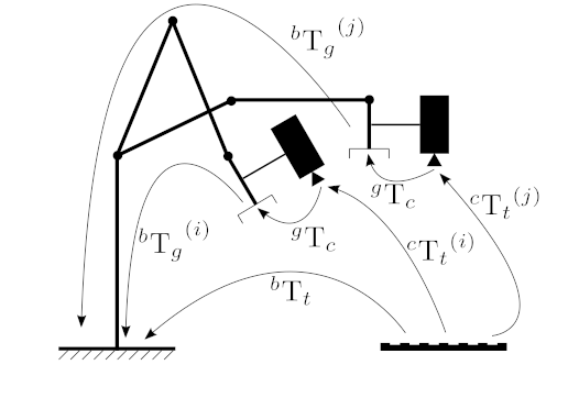
The following picture describes the Hand-Eye calibration problem where the transformation between a camera (“eye”) mounted on a robot gripper (“hand”) has to be estimated. This configuration is called eye-in-hand.
The eye-to-hand configuration consists in a static camera observing a calibration pattern mounted on the robot end-effector. The transformation from the camera to the robot base frame can then be estimated by inputting the suitable transformations to the function, see below.
The calibration procedure is the following:
a static calibration pattern is used to estimate the transformation between the target frame and the camera frame
the robot gripper is moved in order to acquire several poses
for each pose, the homogeneous transformation between the gripper frame and the robot base frame is recorded using for instance the robot kinematics
for each pose, the homogeneous transformation between the calibration target frame and the camera frame is recorded using for instance a pose estimation method (PnP) from 2D-3D point correspondences
The Hand-Eye calibration procedure returns the following homogeneous transformation
This problem is also known as solving the \(\mathbf{A}\mathbf{X}=\mathbf{X}\mathbf{B}\) equation:
for an eye-in-hand configuration
for an eye-to-hand configuration
Note
Additional information can be found on this website.
A minimum of 2 motions with non parallel rotation axes are necessary to determine the hand-eye transformation. So at least 3 different poses are required, but it is strongly recommended to use many more poses.
Parameters
R_gripper2base— Rotation part extracted from the homogeneous matrix that transforms a point expressed in the gripper frame to the robot base frame ( \(_{}^{b}\textrm{T}_g\)). This is a vector (vector<Mat>) that contains the rotation,(3x3)rotation matrices or(3x1)rotation vectors, for all the transformations from gripper frame to robot base frame.t_gripper2base— Translation part extracted from the homogeneous matrix that transforms a point expressed in the gripper frame to the robot base frame ( \(_{}^{b}\textrm{T}_g\)). This is a vector (vector<Mat>) that contains the(3x1)translation vectors for all the transformations from gripper frame to robot base frame.R_target2cam— Rotation part extracted from the homogeneous matrix that transforms a point expressed in the target frame to the camera frame ( \(_{}^{c}\textrm{T}_t\)). This is a vector (vector<Mat>) that contains the rotation,(3x3)rotation matrices or(3x1)rotation vectors, for all the transformations from calibration target frame to camera frame.t_target2cam— Rotation part extracted from the homogeneous matrix that transforms a point expressed in the target frame to the camera frame ( \(_{}^{c}\textrm{T}_t\)). This is a vector (vector<Mat>) that contains the(3x1)translation vectors for all the transformations from calibration target frame to camera frame.R_cam2gripper— Estimated(3x3)rotation part extracted from the homogeneous matrix that transforms a point expressed in the camera frame to the gripper frame ( \(_{}^{g}\textrm{T}_c\)).t_cam2gripper— Estimated(3x1)translation part extracted from the homogeneous matrix that transforms a point expressed in the camera frame to the gripper frame ( \(_{}^{g}\textrm{T}_c\)).method— One of the implemented Hand-Eye calibration method, see cv::HandEyeCalibrationMethod
calibrateMultiview()#
double cv::calibrateMultiview(
InputArrayOfArrays objPoints,
const std::vector< std::vector< Mat > > & imagePoints,
const std::vector< cv::Size > & imageSize,
InputArray detectionMask,
InputArray models,
InputOutputArrayOfArrays Ks,
InputOutputArrayOfArrays distortions,
InputOutputArrayOfArrays Rs,
InputOutputArrayOfArrays Ts,
InputArray flagsForIntrinsics = noArray(),
int flags = 0,
TermCriteria criteria = TermCriteria(TermCriteria::COUNT+TermCriteria::EPS, 100, DBL_EPSILON) )
#include <opencv2/calib.hpp>
Python:
cv.calibrateMultiview(objPoints, imagePoints, imageSize, detectionMask, models, Ks, distortions, Rs, Ts[, flagsForIntrinsics[, flags[, criteria]]]) -> retval, Ks, distortions, Rs, Ts
cv.calibrateMultiviewExtended(objPoints, imagePoints, imageSize, detectionMask, models, Ks, distortions, Rs, Ts[, initializationPairs[, rvecs0[, tvecs0[, perFrameErrors[, flagsForIntrinsics[, flags[, criteria]]]]]]]) -> retval, Ks, distortions, Rs, Ts, initializationPairs, rvecs0, tvecs0, perFrameErrors
This is an overloaded member function, provided for convenience. It differs from the above function only in what argument(s) it accepts.
calibrateMultiview()#
double cv::calibrateMultiview(
InputArrayOfArrays objPoints,
const std::vector< std::vector< Mat > > & imagePoints,
const std::vector< cv::Size > & imageSize,
InputArray detectionMask,
InputArray models,
InputOutputArrayOfArrays Ks,
InputOutputArrayOfArrays distortions,
InputOutputArrayOfArrays Rs,
InputOutputArrayOfArrays Ts,
OutputArray initializationPairs,
OutputArrayOfArrays rvecs0,
OutputArrayOfArrays tvecs0,
OutputArray perFrameErrors,
InputArray flagsForIntrinsics = noArray(),
int flags = 0,
TermCriteria criteria = TermCriteria(TermCriteria::COUNT+TermCriteria::EPS, 100, DBL_EPSILON) )
#include <opencv2/calib.hpp>
Python:
cv.calibrateMultiview(objPoints, imagePoints, imageSize, detectionMask, models, Ks, distortions, Rs, Ts[, flagsForIntrinsics[, flags[, criteria]]]) -> retval, Ks, distortions, Rs, Ts
cv.calibrateMultiviewExtended(objPoints, imagePoints, imageSize, detectionMask, models, Ks, distortions, Rs, Ts[, initializationPairs[, rvecs0[, tvecs0[, perFrameErrors[, flagsForIntrinsics[, flags[, criteria]]]]]]]) -> retval, Ks, distortions, Rs, Ts, initializationPairs, rvecs0, tvecs0, perFrameErrors
Estimates intrinsics and extrinsics (camera pose) for multi-camera system a.k.a multiview calibration.
Output size: (NUM_CAMERAS-1) x 2.
tutorial_multiview_camera_calibration provides a detailed tutorial of using this function. Please refer to it for more information.
Multiview calibration usually requires several cameras to observe the same calibration pattern simultaneously. The fundamental assumption is that relative camera poses are fixed, and then for each frame, only the absolute camera pose for a single camera is needed to fix the camera pose for the multiple cameras
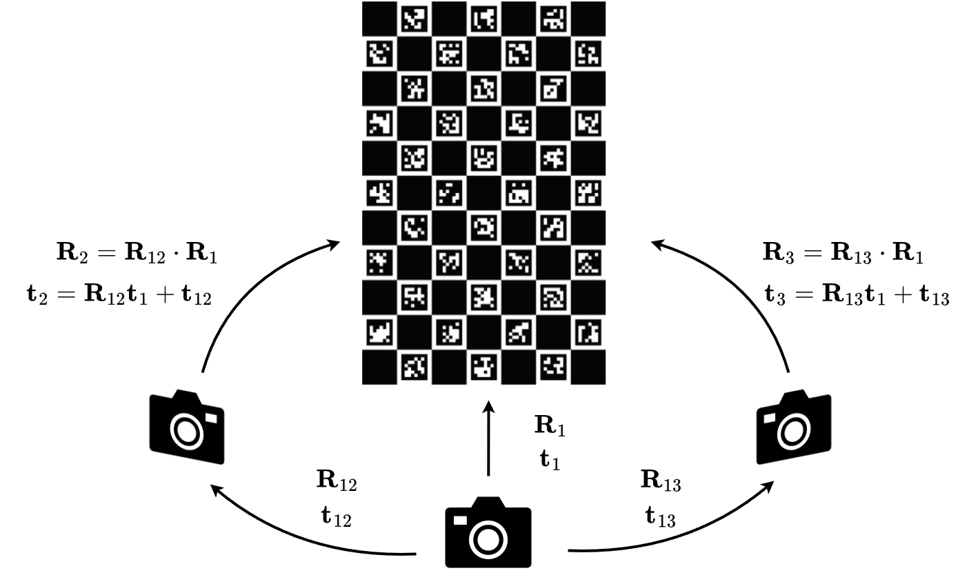
The above illustration shows an example setting for multiview camera calibration.
For each frame, suppose the absolute camera pose for camera \(i\) is \(R_i, t_i\), and the relative camera pose between camera \(i\) and camera \(j\) is \(R_{ij}, t_{ij}\). Suppose \(R_1, t_1\), and \(R_{1i}\) for any \(i\not=1\) are known, then its pose can be calculated by
Since the relative pose between two cameras can be calculated by
This implies that any other relative pose of the form \(R_{ij}, i\not=1\) is redundant. Given this, the total number of poses to determine is (NUM_CAMERAS-1) and NUM_FRAMES. This serves as the foundation of this function.
Similarly to calibrateCamera, the function minimizes the total re-projection error for all the points in all the available views from all cameras.
See also
findChessboardCorners, findCirclesGrid, calibrateCamera, fisheye::calibrate, registerCameras
Parameters
objPoints— Calibration pattern object points. Expected shape: NUM_FRAMES x NUM_POINTS x 3. Supported data type: CV_32F.imagePoints— Detected pattern points on camera images. Expected shape: NUM_CAMERAS x NUM_FRAMES x NUM_POINTS x 2. This function supports partial observation of the calibration pattern. To enable this, set the unobserved image points to be invalid points (eg. (-1., -1.)).imageSize— Images resolution array for each camera.detectionMask— Pattern detection mask. Each value defines if i-camera observes the calibration pattern in j-th frame. Expected size: NUM_CAMERAS x NUM_FRAMES. Expected type: CV_8U.models— indicates camera models for each camera: cv::CALIB_MODEL_PINHOLE or cv::CALIB_MODEL_PINHOLE. Current implementation does not support mix of different camera models. Expected type: CV_8U.flagsForIntrinsics— Flags used for each camera intrinsics calibration. Use per-camera call and theuseIntrinsicsGuessflag to get custom intrinsics calibration for each camera.flags— Common multiview calibration flags. cv::CALIB_USE_INTRINSIC_GUESS and cv::CALIB_USE_EXTRINSIC_GUESS are supported. See CALIB_USE_INTRINSIC_GUESS and otherCALIB_constants. Expected shape: NUM_CAMERAS x 1. Supported data type: CV_32S.Rs— Rotation vectors relative to camera 0, where Rs[0] = 0. Output size: NUM_CAMERAS x 3 x 3.Ts— Estimated translation vectors relative to camera 0, where Ts[0] = 0. Output size: NUM_CAMERAS x 3 x 1.rvecs0— Estimated rotation vectors for camera 0. Output size: NUM_FRAMES x 3 x 1 (may contain null Mat, if the frame is not valid). See Rodrigues.tvecs0— Translation vectors for camera 0. Output size: NUM_FRAMES x 3 x 1. (may contain null Mat, if the frame is not valid).Ks— Estimated floating-point camera intrinsic matrix. Output size: NUM_CAMERAS x 3 x 3.distortions— Distortion coefficients. Output size: NUM_CAMERAS x NUM_PARAMS.perFrameErrors— RMSE value for each visible frame, (-1 for non-visible). Output size: NUM_CAMERAS x NUM_FRAMES.initializationPairs— Pairs with camera indices that were used for initial pairwise stereo calibration.criteria— Termination criteria for the iterative optimization algorithm.
Returns
Overall RMS re-projection error over detectionMask.
calibrateRobotWorldHandEye()#
void cv::calibrateRobotWorldHandEye(
InputArrayOfArrays R_world2cam,
InputArrayOfArrays t_world2cam,
InputArrayOfArrays R_base2gripper,
InputArrayOfArrays t_base2gripper,
OutputArray R_base2world,
OutputArray t_base2world,
OutputArray R_gripper2cam,
OutputArray t_gripper2cam,
RobotWorldHandEyeCalibrationMethod method = CALIB_ROBOT_WORLD_HAND_EYE_SHAH )
#include <opencv2/calib.hpp>
Computes Robot-World/Hand-Eye calibration: \(_{}^{w}\textrm{T}_b\) and \(_{}^{c}\textrm{T}_g\).
The function performs the Robot-World/Hand-Eye calibration using various methods. One approach consists in estimating the rotation then the translation (separable solutions):
M. Shah, Solving the robot-world/hand-eye calibration problem using the kronecker product [270]
Another approach consists in estimating simultaneously the rotation and the translation (simultaneous solutions), with the following implemented method:
A. Li, L. Wang, and D. Wu, Simultaneous robot-world and hand-eye calibration using dual-quaternions and kronecker product [180]
The following picture describes the Robot-World/Hand-Eye calibration problem where the transformations between a robot and a world frame and between a robot gripper (“hand”) and a camera (“eye”) mounted at the robot end-effector have to be estimated.
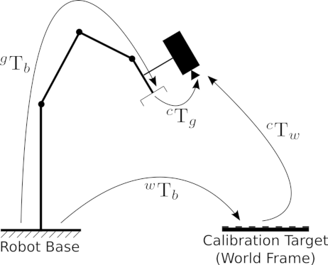
The calibration procedure is the following:
a static calibration pattern is used to estimate the transformation between the target frame and the camera frame
the robot gripper is moved in order to acquire several poses
for each pose, the homogeneous transformation between the gripper frame and the robot base frame is recorded using for instance the robot kinematics
for each pose, the homogeneous transformation between the calibration target frame (the world frame) and the camera frame is recorded using for instance a pose estimation method (PnP) from 2D-3D point correspondences
The Robot-World/Hand-Eye calibration procedure returns the following homogeneous transformations
This problem is also known as solving the \(\mathbf{A}\mathbf{X}=\mathbf{Z}\mathbf{B}\) equation, with:
\(\mathbf{A} \Leftrightarrow \hspace{0.1em} _{}^{c}\textrm{T}_w\)
\(\mathbf{X} \Leftrightarrow \hspace{0.1em} _{}^{w}\textrm{T}_b\)
\(\mathbf{Z} \Leftrightarrow \hspace{0.1em} _{}^{c}\textrm{T}_g\)
\(\mathbf{B} \Leftrightarrow \hspace{0.1em} _{}^{g}\textrm{T}_b\)
Note
At least 3 measurements are required (input vectors size must be greater or equal to 3).
Parameters
R_world2cam— Rotation part extracted from the homogeneous matrix that transforms a point expressed in the world frame to the camera frame ( \(_{}^{c}\textrm{T}_w\)). This is a vector (vector<Mat>) that contains the rotation,(3x3)rotation matrices or(3x1)rotation vectors, for all the transformations from world frame to the camera frame.t_world2cam— Translation part extracted from the homogeneous matrix that transforms a point expressed in the world frame to the camera frame ( \(_{}^{c}\textrm{T}_w\)). This is a vector (vector<Mat>) that contains the(3x1)translation vectors for all the transformations from world frame to the camera frame.R_base2gripper— Rotation part extracted from the homogeneous matrix that transforms a point expressed in the robot base frame to the gripper frame ( \(_{}^{g}\textrm{T}_b\)). This is a vector (vector<Mat>) that contains the rotation,(3x3)rotation matrices or(3x1)rotation vectors, for all the transformations from robot base frame to the gripper frame.t_base2gripper— Rotation part extracted from the homogeneous matrix that transforms a point expressed in the robot base frame to the gripper frame ( \(_{}^{g}\textrm{T}_b\)). This is a vector (vector<Mat>) that contains the(3x1)translation vectors for all the transformations from robot base frame to the gripper frame.R_base2world— Estimated(3x3)rotation part extracted from the homogeneous matrix that transforms a point expressed in the robot base frame to the world frame ( \(_{}^{w}\textrm{T}_b\)).t_base2world— Estimated(3x1)translation part extracted from the homogeneous matrix that transforms a point expressed in the robot base frame to the world frame ( \(_{}^{w}\textrm{T}_b\)).R_gripper2cam— Estimated(3x3)rotation part extracted from the homogeneous matrix that transforms a point expressed in the gripper frame to the camera frame ( \(_{}^{c}\textrm{T}_g\)).t_gripper2cam— Estimated(3x1)translation part extracted from the homogeneous matrix that transforms a point expressed in the gripper frame to the camera frame ( \(_{}^{c}\textrm{T}_g\)).method— One of the implemented Robot-World/Hand-Eye calibration method, see cv::RobotWorldHandEyeCalibrationMethod
initCameraMatrix2D()#
Mat cv::initCameraMatrix2D(
InputArrayOfArrays objectPoints,
InputArrayOfArrays imagePoints,
Size imageSize,
double aspectRatio = 1.0 )
#include <opencv2/calib.hpp>
Python:
cv.initCameraMatrix2D(objectPoints, imagePoints, imageSize[, aspectRatio]) -> retval
Finds an initial camera intrinsic matrix from 3D-2D point correspondences.
The function estimates and returns an initial camera intrinsic matrix for the camera calibration process. Currently, the function only supports planar calibration patterns, which are patterns where each object point has z-coordinate =0.
Parameters
objectPoints— Vector of vectors of the calibration pattern points in the calibration pattern coordinate space. In the old interface all the per-view vectors are concatenated. See calibrateCamera for details.imagePoints— Vector of vectors of the projections of the calibration pattern points. In the old interface all the per-view vectors are concatenated.imageSize— Image size in pixels used to initialize the principal point.aspectRatio— If it is zero or negative, both \(f_x\) and \(f_y\) are estimated independently. Otherwise, \(f_x = f_y \cdot \texttt{aspectRatio}\) .
registerCameras()#
double cv::registerCameras(
InputArrayOfArrays objectPoints1,
InputArrayOfArrays objectPoints2,
InputArrayOfArrays imagePoints1,
InputArrayOfArrays imagePoints2,
InputArray cameraMatrix1,
InputArray distCoeffs1,
CameraModel cameraModel1,
InputArray cameraMatrix2,
InputArray distCoeffs2,
CameraModel cameraModel2,
InputOutputArray R,
InputOutputArray T,
OutputArray E,
OutputArray F,
OutputArray perViewErrors,
int flags = 0,
TermCriteria criteria = TermCriteria(TermCriteria::COUNT+TermCriteria::EPS, 100, 1e-6) )
#include <opencv2/calib.hpp>
Python:
cv.registerCameras(objectPoints1, objectPoints2, imagePoints1, imagePoints2, cameraMatrix1, distCoeffs1, cameraModel1, cameraMatrix2, distCoeffs2, cameraModel2, R, T[, E[, F[, perViewErrors[, flags[, criteria]]]]]) -> retval, R, T, E, F, perViewErrors
This is an overloaded member function, provided for convenience. It differs from the above function only in what argument(s) it accepts.
registerCameras()#
double cv::registerCameras(
InputArrayOfArrays objectPoints1,
InputArrayOfArrays objectPoints2,
InputArrayOfArrays imagePoints1,
InputArrayOfArrays imagePoints2,
InputArray cameraMatrix1,
InputArray distCoeffs1,
CameraModel cameraModel1,
InputArray cameraMatrix2,
InputArray distCoeffs2,
CameraModel cameraModel2,
InputOutputArray R,
InputOutputArray T,
OutputArray E,
OutputArray F,
OutputArrayOfArrays rvecs,
OutputArrayOfArrays tvecs,
OutputArray perViewErrors,
int flags = 0,
TermCriteria criteria = TermCriteria(TermCriteria::COUNT+TermCriteria::EPS, 100, 1e-6) )
#include <opencv2/calib.hpp>
Python:
cv.registerCameras(objectPoints1, objectPoints2, imagePoints1, imagePoints2, cameraMatrix1, distCoeffs1, cameraModel1, cameraMatrix2, distCoeffs2, cameraModel2, R, T[, E[, F[, perViewErrors[, flags[, criteria]]]]]) -> retval, R, T, E, F, perViewErrors
Calibrates a camera pair set up. This function finds the extrinsic parameters between the two cameras.
The function estimates the transformation between two cameras similar to stereo pair calibration. The principle follows closely to stereoCalibrate. To understand the problem of estimating the relative pose between a camera pair, please refer to the description there. The difference for this function is that, camera intrinsics are not optimized and two cameras are not required to have overlapping fields of view as long as they are observing the same calibration target and the absolute positions of each object point are known. 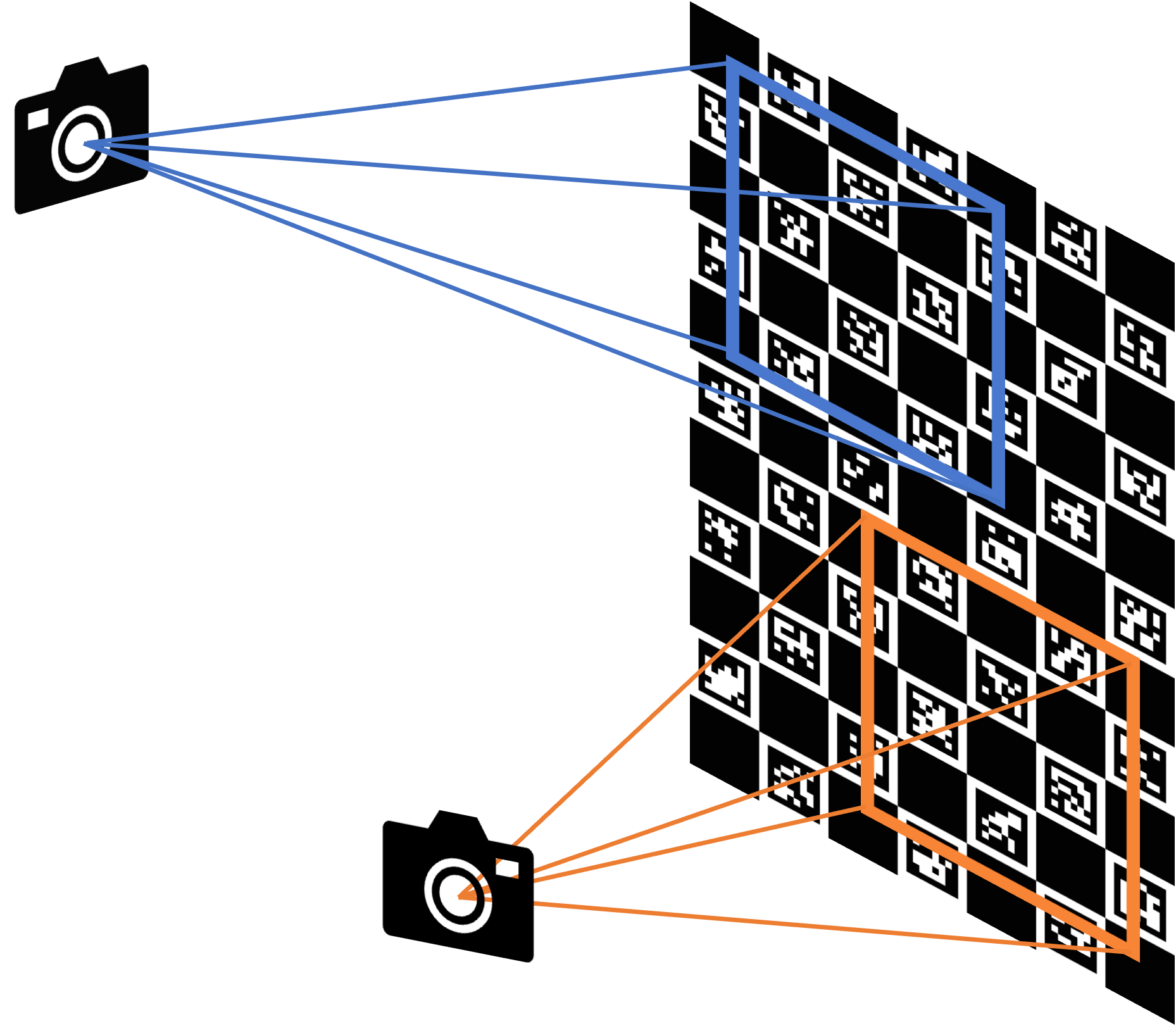
The above illustration shows an example where such a case may become relevant. Additionally, it supports a camera pair with the mixed model (pinhole / fisheye). Similarly to calibrateCamera, the function minimizes the total re-projection error for all the points in all the available views from both cameras.
See also
Parameters
objectPoints1— Vector of vectors of the calibration pattern points for camera 1. A similar structure as objectPoints in calibrateCamera and for each pattern view, both cameras do not need to see the same object points. objectPoints1.size(), imagePoints1.size() nees to be equal,as well as objectPoints1[i].size(), imagePoints1[i].size() need to be equal for each i.objectPoints2— Vector of vectors of the calibration pattern points for camera 2. A similar structure as objectPoints1. objectPoints2.size(), and imagePoints2.size() nees to be equal, as well as objectPoints2[i].size(), imagePoints2[i].size() need to be equal for each i. However, objectPoints1[i].size() and objectPoints2[i].size() are not required to be equal.imagePoints1— Vector of vectors of the projections of the calibration pattern points, observed by the first camera. The same structure as in calibrateCamera.imagePoints2— Vector of vectors of the projections of the calibration pattern points, observed by the second camera. The same structure as in calibrateCamera.cameraMatrix1— Input/output camera intrinsic matrix for the first camera, the same as in calibrateCamera. Furthermore, for the stereo case, additional flags may be used, see below.distCoeffs1— Input/output vector of distortion coefficients, the same as in calibrateCamera.cameraModel1— Flag reflecting the type of model for camera 1 (pinhole / fisheye):CALIB_MODEL_PINHOLE pinhole camera model
CALIB_MODEL_FISHEYE fisheye camera model
cameraMatrix2— Input/output second camera intrinsic matrix for the second camera. See description for cameraMatrix1.distCoeffs2— Input/output lens distortion coefficients for the second camera. See description for distCoeffs1.cameraModel2— Flag reflecting the type of model for camera 2 (pinhole / fisheye). See description for cameraModel1.R— Output rotation matrix. Together with the translation vector T, this matrix brings points given in the first camera’s coordinate system to points in the second camera’s coordinate system. In more technical terms, the tuple of R and T performs a change of basis from the first camera’s coordinate system to the second camera’s coordinate system. Due to its duality, this tuple is equivalent to the position of the first camera with respect to the second camera coordinate system.T— Output translation vector, see description above.E— Output essential matrix.F— Output fundamental matrix.rvecs— Output vector of rotation vectors ( Rodrigues ) estimated for each pattern view in the coordinate system of the first camera of the stereo pair (e.g. std::vector<cv::Mat>). More in detail, each i-th rotation vector together with the corresponding i-th translation vector (see the next output parameter description) brings the calibration pattern from the object coordinate space (in which object points are specified) to the camera coordinate space of the first camera of the stereo pair. In more technical terms, the tuple of the i-th rotation and translation vector performs a change of basis from object coordinate space to the camera coordinate space of the first camera of the stereo pair.tvecs— Output vector of translation vectors estimated for each pattern view, see parameter description of previous output parameter ( rvecs ).perViewErrors— Output vector of the RMS re-projection error estimated for each pattern view.flags— Different flags that may be zero or a combination of the following values:CALIB_USE_EXTRINSIC_GUESS R and T contain valid initial values that are optimized further.
criteria— Termination criteria for the iterative optimization algorithm.
Returns
the final value of the re-projection error.
stereoCalibrate()#
double cv::stereoCalibrate(
InputArrayOfArrays objectPoints,
InputArrayOfArrays imagePoints1,
InputArrayOfArrays imagePoints2,
InputOutputArray cameraMatrix1,
InputOutputArray distCoeffs1,
InputOutputArray cameraMatrix2,
InputOutputArray distCoeffs2,
Size imageSize,
InputOutputArray R,
InputOutputArray T,
OutputArray E,
OutputArray F,
OutputArray perViewErrors,
int flags = CALIB_FIX_INTRINSIC,
TermCriteria criteria = TermCriteria(TermCriteria::COUNT+TermCriteria::EPS, 30, 1e-6) )
#include <opencv2/calib.hpp>
Python:
cv.stereoCalibrate(objectPoints, imagePoints1, imagePoints2, cameraMatrix1, distCoeffs1, cameraMatrix2, distCoeffs2, imageSize[, R[, T[, E[, F[, flags[, criteria]]]]]]) -> retval, cameraMatrix1, distCoeffs1, cameraMatrix2, distCoeffs2, R, T, E, F
cv.stereoCalibrate(objectPoints, imagePoints1, imagePoints2, cameraMatrix1, distCoeffs1, cameraMatrix2, distCoeffs2, imageSize, R, T[, E[, F[, perViewErrors[, flags[, criteria]]]]]) -> retval, cameraMatrix1, distCoeffs1, cameraMatrix2, distCoeffs2, R, T, E, F, perViewErrors
cv.stereoCalibrateExtended(objectPoints, imagePoints1, imagePoints2, cameraMatrix1, distCoeffs1, cameraMatrix2, distCoeffs2, imageSize, R, T[, E[, F[, rvecs[, tvecs[, perViewErrors[, flags[, criteria]]]]]]]) -> retval, cameraMatrix1, distCoeffs1, cameraMatrix2, distCoeffs2, R, T, E, F, rvecs, tvecs, perViewErrors
This is an overloaded member function, provided for convenience. It differs from the above function only in what argument(s) it accepts.
stereoCalibrate()#
double cv::stereoCalibrate(
InputArrayOfArrays objectPoints,
InputArrayOfArrays imagePoints1,
InputArrayOfArrays imagePoints2,
InputOutputArray cameraMatrix1,
InputOutputArray distCoeffs1,
InputOutputArray cameraMatrix2,
InputOutputArray distCoeffs2,
Size imageSize,
InputOutputArray R,
InputOutputArray T,
OutputArray E,
OutputArray F,
OutputArrayOfArrays rvecs,
OutputArrayOfArrays tvecs,
OutputArray perViewErrors,
int flags = CALIB_FIX_INTRINSIC,
TermCriteria criteria = TermCriteria(TermCriteria::COUNT+TermCriteria::EPS, 100, 1e-6) )
#include <opencv2/calib.hpp>
Python:
cv.stereoCalibrate(objectPoints, imagePoints1, imagePoints2, cameraMatrix1, distCoeffs1, cameraMatrix2, distCoeffs2, imageSize[, R[, T[, E[, F[, flags[, criteria]]]]]]) -> retval, cameraMatrix1, distCoeffs1, cameraMatrix2, distCoeffs2, R, T, E, F
cv.stereoCalibrate(objectPoints, imagePoints1, imagePoints2, cameraMatrix1, distCoeffs1, cameraMatrix2, distCoeffs2, imageSize, R, T[, E[, F[, perViewErrors[, flags[, criteria]]]]]) -> retval, cameraMatrix1, distCoeffs1, cameraMatrix2, distCoeffs2, R, T, E, F, perViewErrors
cv.stereoCalibrateExtended(objectPoints, imagePoints1, imagePoints2, cameraMatrix1, distCoeffs1, cameraMatrix2, distCoeffs2, imageSize, R, T[, E[, F[, rvecs[, tvecs[, perViewErrors[, flags[, criteria]]]]]]]) -> retval, cameraMatrix1, distCoeffs1, cameraMatrix2, distCoeffs2, R, T, E, F, rvecs, tvecs, perViewErrors
Calibrates a stereo camera set up. This function finds the intrinsic parameters for each of the two cameras and the extrinsic parameters between the two cameras.
The function estimates the transformation between two cameras making a stereo pair. If one computes the poses of an object relative to the first camera and to the second camera, ( \(R_1\), \(T_1\) ) and ( \(R_2\), \(T_2\)), respectively, for a stereo camera where the relative position and orientation between the two cameras are fixed, then those poses definitely relate to each other. This means, if the relative position and orientation ( \(R\), \(T\)) of the two cameras is known, it is possible to compute ( \(R_2\), \(T_2\)) when ( \(R_1\), \(T_1\)) is given. This is what the described function does. It computes ( \(R\), \(T\)) such that:
Therefore, one can compute the coordinate representation of a 3D point for the second camera’s coordinate system when given the point’s coordinate representation in the first camera’s coordinate system:
Optionally, it computes the essential matrix E:
where \(T_i\) are components of the translation vector \(T\) : \(T=[T_0, T_1, T_2]^T\) . And the function can also compute the fundamental matrix F:
Besides the stereo-related information, the function can also perform a full calibration of each of the two cameras. However, due to the high dimensionality of the parameter space and noise in the input data, the function can diverge from the correct solution. If the intrinsic parameters can be estimated with high accuracy for each of the cameras individually (for example, using calibrateCamera ), you are recommended to do so and then pass CALIB_FIX_INTRINSIC flag to the function along with the computed intrinsic parameters. Otherwise, if all the parameters are estimated at once, it makes sense to restrict some parameters, for example, pass CALIB_SAME_FOCAL_LENGTH and CALIB_ZERO_TANGENT_DIST flags, which is usually a reasonable assumption.
Similarly to calibrateCamera, the function minimizes the total re-projection error for all the points in all the available views from both cameras. The function returns the final value of the re-projection error.
Parameters
objectPoints— Vector of vectors of the calibration pattern points. The same structure as in calibrateCamera. For each pattern view, both cameras need to see the same object points. Therefore, objectPoints.size(), imagePoints1.size(), and imagePoints2.size() need to be equal as well as objectPoints[i].size(), imagePoints1[i].size(), and imagePoints2[i].size() need to be equal for each i.imagePoints1— Vector of vectors of the projections of the calibration pattern points, observed by the first camera. The same structure as in calibrateCamera.imagePoints2— Vector of vectors of the projections of the calibration pattern points, observed by the second camera. The same structure as in calibrateCamera.cameraMatrix1— Input/output camera intrinsic matrix for the first camera, the same as in calibrateCamera. Furthermore, for the stereo case, additional flags may be used, see below.distCoeffs1— Input/output vector of distortion coefficients, the same as in calibrateCamera.cameraMatrix2— Input/output second camera intrinsic matrix for the second camera. See description for cameraMatrix1.distCoeffs2— Input/output lens distortion coefficients for the second camera. See description for distCoeffs1.imageSize— Size of the image used only to initialize the camera intrinsic matrices.R— Output rotation matrix. Together with the translation vector T, this matrix brings points given in the first camera’s coordinate system to points in the second camera’s coordinate system. In more technical terms, the tuple of R and T performs a change of basis from the first camera’s coordinate system to the second camera’s coordinate system. Due to its duality, this tuple is equivalent to the position of the first camera with respect to the second camera coordinate system.T— Output translation vector, see description above.E— Output essential matrix.F— Output fundamental matrix.rvecs— Output vector of rotation vectors ( Rodrigues ) estimated for each pattern view in the coordinate system of the first camera of the stereo pair (e.g. std::vector<cv::Mat>). More in detail, each i-th rotation vector together with the corresponding i-th translation vector (see the next output parameter description) brings the calibration pattern from the object coordinate space (in which object points are specified) to the camera coordinate space of the first camera of the stereo pair. In more technical terms, the tuple of the i-th rotation and translation vector performs a change of basis from object coordinate space to camera coordinate space of the first camera of the stereo pair.tvecs— Output vector of translation vectors estimated for each pattern view, see parameter description of previous output parameter ( rvecs ).perViewErrors— Output vector of the RMS re-projection error estimated for each pattern view.flags— Different flags that may be zero or a combination of the following values:CALIB_FIX_INTRINSIC Fix cameraMatrix? and distCoeffs? so that only R, T, E, and F matrices are estimated.
CALIB_USE_INTRINSIC_GUESS Optimize some or all of the intrinsic parameters according to the specified flags. Initial values are provided by the user.
CALIB_USE_EXTRINSIC_GUESS R and T contain valid initial values that are optimized further. Otherwise R and T are initialized to the median value of the pattern views (each dimension separately).
CALIB_FIX_PRINCIPAL_POINT Fix the principal points during the optimization.
CALIB_FIX_FOCAL_LENGTH Fix \(f^{(j)}_x\) and \(f^{(j)}_y\) .
CALIB_FIX_ASPECT_RATIO Optimize \(f^{(j)}_y\) . Fix the ratio \(f^{(j)}_x/f^{(j)}_y\)
CALIB_SAME_FOCAL_LENGTH Enforce \(f^{(0)}_x=f^{(1)}_x\) and \(f^{(0)}_y=f^{(1)}_y\) .
CALIB_ZERO_TANGENT_DIST Set tangential distortion coefficients for each camera to zeros and fix there.
CALIB_FIX_K1,…, CALIB_FIX_K6 Do not change the corresponding radial distortion coefficient during the optimization. If CALIB_USE_INTRINSIC_GUESS is set, the coefficient from the supplied distCoeffs matrix is used. Otherwise, it is set to 0.
CALIB_RATIONAL_MODEL Enable coefficients k4, k5, and k6. To provide the backward compatibility, this extra flag should be explicitly specified to make the calibration function use the rational model and return 8 coefficients. If the flag is not set, the function computes and returns only 5 distortion coefficients.
CALIB_THIN_PRISM_MODEL Coefficients s1, s2, s3 and s4 are enabled. To provide the backward compatibility, this extra flag should be explicitly specified to make the calibration function use the thin prism model and return 12 coefficients. If the flag is not set, the function computes and returns only 5 distortion coefficients.
CALIB_FIX_S1_S2_S3_S4 The thin prism distortion coefficients are not changed during the optimization. If CALIB_USE_INTRINSIC_GUESS is set, the coefficient from the supplied distCoeffs matrix is used. Otherwise, it is set to 0.
CALIB_TILTED_MODEL Coefficients tauX and tauY are enabled. To provide the backward compatibility, this extra flag should be explicitly specified to make the calibration function use the tilted sensor model and return 14 coefficients. If the flag is not set, the function computes and returns only 5 distortion coefficients.
CALIB_FIX_TAUX_TAUY The coefficients of the tilted sensor model are not changed during the optimization. If CALIB_USE_INTRINSIC_GUESS is set, the coefficient from the supplied distCoeffs matrix is used. Otherwise, it is set to 0.
criteria— Termination criteria for the iterative optimization algorithm.
stereoCalibrate()#
double cv::stereoCalibrate(
InputArrayOfArrays objectPoints,
InputArrayOfArrays imagePoints1,
InputArrayOfArrays imagePoints2,
InputOutputArray cameraMatrix1,
InputOutputArray distCoeffs1,
InputOutputArray cameraMatrix2,
InputOutputArray distCoeffs2,
Size imageSize,
OutputArray R,
OutputArray T,
OutputArray E,
OutputArray F,
int flags = CALIB_FIX_INTRINSIC,
TermCriteria criteria = TermCriteria(TermCriteria::COUNT+TermCriteria::EPS, 100, 1e-6) )
#include <opencv2/calib.hpp>
Python:
cv.stereoCalibrate(objectPoints, imagePoints1, imagePoints2, cameraMatrix1, distCoeffs1, cameraMatrix2, distCoeffs2, imageSize[, R[, T[, E[, F[, flags[, criteria]]]]]]) -> retval, cameraMatrix1, distCoeffs1, cameraMatrix2, distCoeffs2, R, T, E, F
cv.stereoCalibrate(objectPoints, imagePoints1, imagePoints2, cameraMatrix1, distCoeffs1, cameraMatrix2, distCoeffs2, imageSize, R, T[, E[, F[, perViewErrors[, flags[, criteria]]]]]) -> retval, cameraMatrix1, distCoeffs1, cameraMatrix2, distCoeffs2, R, T, E, F, perViewErrors
cv.stereoCalibrateExtended(objectPoints, imagePoints1, imagePoints2, cameraMatrix1, distCoeffs1, cameraMatrix2, distCoeffs2, imageSize, R, T[, E[, F[, rvecs[, tvecs[, perViewErrors[, flags[, criteria]]]]]]]) -> retval, cameraMatrix1, distCoeffs1, cameraMatrix2, distCoeffs2, R, T, E, F, rvecs, tvecs, perViewErrors
This is an overloaded member function, provided for convenience. It differs from the above function only in what argument(s) it accepts.
Macro Definition Documentation#
CALIB_NINTRINSIC#
#define CALIB_NINTRINSIC
#include <opencv2/calib.hpp>
Value:
18
Maximal size of camera internal parameters (initrinsics) vector.