|
OpenCV
4.5.1
Open Source Computer Vision
|
Prev Tutorial: Smoothing Images
Next Tutorial: More Morphology Transformations
| Original author | Ana Huamán |
| Compatibility | OpenCV >= 3.0 |
In this tutorial you will learn how to:
We will explain dilation and erosion briefly, using the following image as an example:

Take the above image as an example. Applying dilation we can get:

Analagously to the example for dilation, we can apply the erosion operator to the original image (shown above). You can see in the result below that the bright areas of the image get thinner, whereas the dark zones gets bigger.

This tutorial's code is shown below. You can also download it here
This tutorial's code is shown below. You can also download it here
This tutorial's code is shown below. You can also download it here
Most of the material shown here is trivial (if you have any doubt, please refer to the tutorials in previous sections). Let's check the general structure of the C++ program:
Every time we move any slider, the user's function Erosion or Dilation will be called and it will update the output image based on the current trackbar values.
Let's analyze these two functions:
The function that performs the erosion operation is cv::erode . As we can see, it receives three arguments:
element: This is the kernel we will use to perform the operation. If we do not specify, the default is a simple 3x3 matrix. Otherwise, we can specify its shape. For this, we need to use the function cv::getStructuringElement :
We can choose any of three shapes for our kernel:
Then, we just have to specify the size of our kernel and the anchor point. If not specified, it is assumed to be in the center.
That is all. We are ready to perform the erosion of our image.
The code is below. As you can see, it is completely similar to the snippet of code for erosion. Here we also have the option of defining our kernel, its anchor point and the size of the operator to be used.
Most of the material shown here is trivial (if you have any doubt, please refer to the tutorials in previous sections). Let's check however the general structure of the java class. There are 4 main parts in the java class:
addComponentsToPane method, which fills out the windowupdate method, which determines what happens when the user changes any valuemain method, which is the entry point of the programIn this tutorial we will focus on the addComponentsToPane and update methods. However, for completion the steps followed in the constructor are:
addComponentsToPaneThe components were added by the following method:
In short we
The action and state changed listeners added call at the end the update method which updates the image based on the current slider values. So every time we move any slider, the update method is triggered.
To update the image we used the following implementation:
In other words we
doErosionLet's analyze the erode and dilate methods:
The function that performs the erosion operation is cv::erode . As we can see, it receives three arguments:
element: This is the kernel we will use to perform the operation. For specifying the shape, we need to use the function cv::getStructuringElement :
We can choose any of three shapes for our kernel:
Together with the shape we specify the size of our kernel and the anchor point. If the anchor point is not specified, it is assumed to be in the center.
That is all. We are ready to perform the erosion of our image.
The code is below. As you can see, it is completely similar to the snippet of code for erosion. Here we also have the option of defining our kernel, its anchor point and the size of the operator to be used.
Most of the material shown here is trivial (if you have any doubt, please refer to the tutorials in previous sections). Let's check the general structure of the python script:
Every time we move any slider, the user's function erosion or dilation will be called and it will update the output image based on the current trackbar values.
Let's analyze these two functions:
The function that performs the erosion operation is cv::erode . As we can see, it receives two arguments and returns the processed image:
Then, we just have to specify the size of our kernel and the anchor point. If the anchor point not specified, it is assumed to be in the center.
That is all. We are ready to perform the erosion of our image.
The code is below. As you can see, it is completely similar to the snippet of code for erosion. Here we also have the option of defining our kernel, its anchor point and the size of the operator to be used.
Compile the code above and execute it (or run the script if using python) with an image as argument. If you do not provide an image as argument the default sample image (LinuxLogo.jpg) will be used.
For instance, using this image:

We get the results below. Varying the indices in the Trackbars give different output images, naturally. Try them out! You can even try to add a third Trackbar to control the number of iterations.
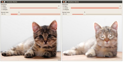
(depending on the programming language the output might vary a little or be only 1 window)
 1.8.13