|
OpenCV
3.1.0
Open Source Computer Vision
|
|
OpenCV
3.1.0
Open Source Computer Vision
|
Pose estimation is of great importance in many computer vision applications: robot navigation, augmented reality, and many more. This process is based on finding correspondences between points in the real environment and their 2d image projection. This is usually a difficult step, and thus it is common the use of synthetic or fiducial markers to make it easier.
One of the most popular approach is the use of binary square fiducial markers. The main benefit of these markers is that a single marker provides enough correspondences (its four corners) to obtain the camera pose. Also, the inner binary codification makes them specially robust, allowing the possibility of applying error detection and correction techniques.
The aruco module is based on the ArUco library, a popular library for detection of square fiducial markers developed by Rafael Muñoz and Sergio Garrido:
S. Garrido-Jurado, R. Muñoz-Salinas, F. J. Madrid-Cuevas, and M. J. Marín-Jiménez. 2014. "Automatic generation and detection of highly reliable fiducial markers under occlusion". Pattern Recogn. 47, 6 (June 2014), 2280-2292. DOI=10.1016/j.patcog.2014.01.005
The aruco functionalities are included in: ``` c++ #include <opencv2/aruco.hpp> ```
An ArUco marker is a synthetic square marker composed by a wide black border and a inner binary matrix which determines its identifier (id). The black border facilitates its fast detection in the image and the binary codification allows its identification and the application of error detection and correction techniques. The marker size determines the size of the internal matrix. For instance a marker size of 4x4 is composed by 16 bits.
Some examples of ArUco markers:

It must be noted that a marker can be found rotated in the environment, however, the detection process needs to be able to determine its original rotation, so that each corner is identified unequivocally. This is also done based on the binary codification.
A dictionary of markers is a set of markers that are considered in an specific application. It is simply the list of binary codifications of each of its markers.
The main properties of a dictionary are the dictionary size and the marker size.
The aruco module includes some predefined dictionaries covering a range of different dictionary sizes and marker sizes.
One may think that the marker id is the number obtained from converting the binary codification to a decimal base number. However, this is not possible since for high marker sizes the number of bits is too high and managing so huge numbers is not practical. Instead, a marker id is simply the marker index inside the dictionary it belongs to. For instance, the first 5 markers inside a dictionary has the ids: 0, 1, 2, 3 and 4.
More information about dictionaries is provided in the "Selecting a dictionary" section.
Before their detection, markers need to be printed in order to be placed in the environment. Marker images can be generated using the drawMarker() function.
For example, lets analyze the following call:
``` c++ cv::Mat markerImage; cv::aruco::Dictionary dictionary = cv::aruco::getPredefinedDictionary(cv::aruco::DICT_6X6_250); cv::aruco::drawMarker(dictionary, 23, 200, markerImage, 1); ```
First, the Dictionary object is created by choosing one of the predefined dictionaries in the aruco module. Concretely, this dictionary is composed by 250 markers and a marker size of 6x6 bits (DICT_6X6_250).
The parameters of drawMarker are:
Dictionary object previously created.DICT_6X6_250. Note that each dictionary is composed by a different number of markers. In this case, the valid ids go from 0 to 249. Any specific id out of the valid range will produce an exception.The generated image is:

A full working example is included in the create_marker.cpp inside the module samples folder.
Given an image where some ArUco markers are visible, the detection process has to return a list of detected markers. Each detected marker includes:
The marker detection process is comprised by two main steps:
Consider the following image:

These are the detected markers (in green):

And these are the marker candidates that have been rejected during the identification step (in pink):

In the aruco module, the detection is performed in the detectMarkers() function. This function is the most important in the module, since all the rest of functionalities are based on the previous detected markers returned by detectMarkers().
An example of marker detection:
``` c++ cv::Mat inputImage; ... vector< int > markerIds; vector< vector<Point2f> > markerCorners, rejectedCandidates; cv::aruco::DetectorParameters parameters; cv::aruco::Dictionary dictionary = cv::aruco::getPredefinedDictionary(cv::aruco::DICT_6X6_250); cv::aruco::detectMarkers(inputImage, dictionary, markerCorners, markerIds, parameters, rejectedCandidates); ```
The parameters of detectMarkers are:
DICT_6X6_250).markerCorners and markerIds structures:markerCorners is the list of corners of the detected markers. For each marker, its four corners are returned in their original order (which is clockwise starting with top left). So, the first corner is the top left corner, followed by the top right, bottom right and bottom left.markerIds is the list of ids of each of the detected markers in markerCorners. Note that the returned markerCorners and markerIds vectors have the same sizes.DetectionParameters. This object includes all the parameters that can be customized during the detection process. This parameters are commented in detail in the next section.rejectedCandidates, is a returned list of marker candidates, i.e. those squares that have been found but they do not present a valid codification. Each candidate is also defined by its four corners, and its format is the same than the markerCorners parameter. This parameter can be omitted and is only useful for debugging purposes and for 'refind' strategies (see refineDetectedMarkers() ).The next thing you probably want to do after detectMarkers() is checking that your markers have been correctly detected. Fortunately, the aruco module provides a function to draw the detected markers in the input image, this function is drawDetectedMarkers(). For example:
``` c++ cv::Mat outputImage cv::aruco::drawDetectedMarkers(image, markerCorners, markerIds); ```
image is the input/output image where the markers will be drawn (it will normally be the same image where the markers were detected).markerCorners and markerIds are the structures of the detected markers in the same format provided by the detectMarkers() function.
Note that this function is only provided for visualization and its use can be perfectly omitted.
With these two functions we can create a basic marker detection loop to detect markers from our camera:
``` c++ cv::VideoCapture inputVideo; inputVideo.open(0); cv::aruco::Dictionary dictionary = cv::aruco::getPredefinedDictionary(cv::aruco::DICT_6X6_250); while (inputVideo.grab()) { cv::Mat image, imageCopy; inputVideo.retrieve(image); image.copyTo(imageCopy);
std::vector<int> ids; std::vector<std::vector<cv::Point2f> > corners; cv::aruco::detectMarkers(image, dictionary, corners, ids);
// if at least one marker detected if (ids.size() > 0) cv::aruco::drawDetectedMarkers(imageCopy, corners, ids);
cv::imshow("out", imageCopy); char key = (char) cv::waitKey(waitTime); if (key == 27) break; } ```
Note that some of the optional parameters have been omitted, like the detection parameter object or the output vector of rejected candidates.
A full working example is included in the detect_markers.cpp inside the module samples folder.
The next thing you probably want to do after detecting the markers is to obtain the camera pose from them.
To perform camera pose estimation you need to know the calibration parameters of your camera. This is the camera matrix and distortion coefficients. If you do not know how to calibrate your camera, you can take a look to the calibrateCamera() function and the Calibration tutorial of OpenCV. You can also calibrate your camera using the aruco module as it is explained in the Calibration with aruco tutorial. Note that this only need to be done once unless the camera optics are modified (for instance changing its focus).
At the end, what you get after the calibration is the camera matrix: a matrix of 3x3 elements with the focal distances and the camera center coordinates (a.k.a intrinsic parameters), and the distortion coefficients: a vector of 5 elements or more that models the distortion produced by your camera.
When you estimate the pose with ArUco markers, you can estimate the pose of each marker individually. If you want to estimate one pose from a set of markers, what you want to use is aruco Boards (see ArUco Boards tutorial).
The camera pose respect to a marker is the 3d transformation from the marker coordinate system to the camera coordinate system. It is specified by a rotation and a translation vector (see solvePnP() function for more information).
The aruco module provides a function to estimate the poses of all the detected markers:
``` c++ Mat cameraMatrix, distCoeffs; ... vector< Vec3d > rvecs, tvecs; cv::aruco::estimatePoseSingleMarkers(corners, 0.05, cameraMatrix, distCoeffs, rvecs, tvecs); ```
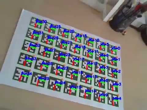
corners parameter is the vector of marker corners returned by the detectMarkers() function.cameraMatrix and distCoeffs are the camera calibration parameters that need to be known a priori.rvecs and tvecs are the rotation and translation vectors respectively, for each of the markers in corners.The marker coordinate system that is assumed by this function is placed at the center of the marker with the Z axis pointing out, as in the following image. Axis-color correspondences are X:red, Y:green, Z:blue.

The aruco module provides a function to draw the axis as in the image above, so pose estimation can be checked:
``` c++ cv::aruco::drawAxis(image, cameraMatrix, distCoeffs, rvec, tvec, 0.1); ```
image is the input/output image where the axis will be drawn (it will normally be the same image where the markers were detected).cameraMatrix and distCoeffs are the camera calibration parameters.rvec and tvec are the pose parameters whose axis want to be drawn.A basic full example for pose estimation from single markers:
``` c++ cv::VideoCapture inputVideo; inputVideo.open(0);
cv::Mat cameraMatrix, distCoeffs; // camera parameters are read from somewhere readCameraParameters(cameraMatrix, distCoeffs);
cv::aruco::Dictionary dictionary = cv::aruco::getPredefinedDictionary(cv::aruco::DICT_6X6_250);
while (inputVideo.grab()) { cv::Mat image, imageCopy; inputVideo.retrieve(image); image.copyTo(imageCopy);
std::vector<int> ids; std::vector<std::vector<cv::Point2f> > corners; cv::aruco::detectMarkers(image, dictionary, corners, ids);
// if at least one marker detected if (ids.size() > 0) { cv::aruco::drawDetectedMarkers(imageCopy, corners, ids);
vector< Mat > rvecs, tvecs; cv::aruco::estimatePoseSingleMarkers(corners, 0.05, cameraMatrix, distCoeffs, rvecs, tvecs); // draw axis for each marker for(int i=0; i<ids.size(); i++) cv::aruco::drawAxis(imageCopy, cameraMatrix, distCoeffs, rvecs[i], tvecs[i], 0.1); }
cv::imshow("out", imageCopy); char key = (char) cv::waitKey(waitTime); if (key == 27) break; } ```
Sample video:
A full working example is included in the detect_markers.cpp inside the module samples folder.
The aruco module provides the Dictionary class to represent a dictionary of markers.
Apart of the marker size and the number of markers in the dictionary, there is another important dictionary parameter, the inter-marker distance. The inter-marker distance is the minimum distance among its markers and it determines the error detection and correction capabilities of the dictionary.
In general, lower dictionary sizes and higher marker sizes increase the inter-marker distance and vice-versa. However, the detection of markers with higher sizes is more complex, due to the higher amount of bits that need to be extracted from the image.
For instance, if you need only 10 markers in your application, it is better to use a dictionary only composed by those 10 markers than using one dictionary composed by 1000 markers. The reason is that the dictionary composed by 10 markers will have a higher inter-marker distance and, thus, it will be more robust to errors.
As a consequence, the aruco module includes several ways to select your dictionary of markers, so that you can increase your system robustness:
This is the easiest way to select a dictionary. The aruco module includes a set of predefined dictionaries of a variety of marker sizes and number of markers. For instance:
``` c++ cv::aruco::Dictionary dictionary = cv::aruco::getPredefinedDictionary(cv::aruco::DICT_6X6_250); ```
DICT_6X6_250 is an example of predefined dictionary of markers with 6x6 bits and a total of 250 markers.
From all the provided dictionaries, it is recommended to choose the smaller one that fits to your application. For instance, if you need 200 markers of 6x6 bits, it is better to use DICT_6X6_250 than DICT_6X6_1000. The smaller the dictionary, the higher the inter-marker distance.
The dictionary can be generated automatically to adjust to the desired number of markers and bits, so that the inter-marker distance is optimized:
``` c++ cv::aruco::Dictionary dictionary = cv::aruco::generateCustomDictionary(36, 5); ```
This will generate a customized dictionary composed by 36 markers of 5x5 bits. The process can take several seconds, depending on the parameters (it is slower for larger dictionaries and higher number of bits).
Finally, the dictionary can be configured manually, so that any codification can be employed. To do that, the Dictionary object parameters need to be assigned manually. It must be noted that, unless you have a special reason to do this manually, it is preferable to use one of the previous alternatives.
The Dictionary parameters are:
``` c++ class Dictionary { public:
Mat bytesList; int markerSize; int maxCorrectionBits; // maximum number of bits that can be corrected
...
}
```
bytesList is the array that contains all the information about the marker codes. markerSize is the size of each marker dimension (for instance, 5 for markers with 5x5 bits). Finally, maxCorrectionBits is the maximum number of erroneous bits that can be corrected during the marker detection. If this value is too high, it can lead to a high amount of false positives.
Each row in bytesList represents one of the dictionary markers. However, the markers are not stored in its binary form, instead they are stored in a special format to simplificate their detection.
Fortunately, a marker can be easily transformed to this form using the static method Dictionary::getByteListFromBits().
For example:
``` c++ Dictionary dictionary; // markers of 6x6 bits dictionary.markerSize = 6; // maximum number of bit corrections dictionary.maxCorrectionBits = 3;
// lets create a dictionary of 100 markers for(int i=0; i<100; i++) // assume generateMarkerBits() generate a new marker in binary format, so that // markerBits is a 6x6 matrix of CV_8UC1 type, only containing 0s and 1s cv::Mat markerBits = generateMarkerBits(); cv::Mat markerCompressed = getByteListFromBits(markerBits); // add the marker as a new row dictionary.bytesList.push_back(markerCompressed); }
```
One of the parameters of detectMarkers() function is a DetectorParameters object. This object includes all the options that can be customized during the marker detection process.
In this section, all these parameters are commented. The parameters can be classified depending on the process they are involved:
One of the first steps of the marker detection process is an adaptive thresholding of the input image.
For instance, the thresholded image for the sample image used above is:

This thresholding can be customized in the following parameters:
int adaptiveThreshWinSizeMin, int adaptiveThreshWinSizeMax, int adaptiveThreshWinSizeStepThe adaptiveThreshWinSizeMin and adaptiveThreshWinSizeMax parameters represent the interval where the thresholding window sizes (in pixels) are selected for the adaptive thresholding (see OpenCV threshold() function for more details).
The parameter adaptiveThreshWinSizeStep indicates the increments on the window size from adaptiveThreshWinSizeMin to adaptiveThreshWinSizeMax```.
For instance, for the values adaptiveThreshWinSizeMin = 5 and adaptiveThreshWinSizeMax= 21 and adaptiveThreshWinSizeStep``` = 4, there will be 5 thresholding steps with window sizes 5, 9, 13, 17 and 21. On each thresholding image, marker candidates will be extracted.
Low values of window size can 'break' the marker border if the marker size is too large, and it would not be detected, like in the following image:

On the other hand, too high values can produce the same effect if the markers are too small, and it can also reduce the performance. Moreover the process would tend to a global thresholding, losing the adaptive benefits.
The simplest case is using the same value for adaptiveThreshWinSizeMin and adaptiveThreshWinSizeMax, which produces a single thresholding step. However, it is usually better using a range of values for the window size, although many thresholding steps can also reduce the performance considerably.
Default values:
adaptiveThreshWinSizeMin: 3, adaptiveThreshWinSizeMax: 23, adaptiveThreshWinSizeStep: 10
double adaptiveThreshConstantThis parameter represents the constant value added in the thresholding condition (see OpenCV threshold() function for more details). Its default value is a good option in most cases.
Default value: 7
After thresholding, contours are detected. However, not all contours are considered as marker candidates. They are filtered out in different steps so that contours that are very unlikely to be markers are discarded. The parameters in this section customize this filtering process.
It must be noted that in most cases it is a question of balance between detection capacity and performance. All the considered contours will be processed in the following stages, which usually have a higher computational cost. So, it is preferred to discard wrong candidates in this stage than in the later stages.
On the other hand, if the filtering conditions are too strict, the real marker contours could be discarded and, hence, not detected.
double minMarkerPerimeterRate, double maxMarkerPerimeterRateThese parameters determine the minimum and maximum size of a marker, concretely the maximum and minimum marker perimeter. They are not specified in absolute pixels values, instead they are specified relative to the maximum dimension of the input image.
For instance, a image with size 640x480 and a minimum relative marker perimeter of 0.05 will lead to a minimum marker perimeter of 640x0.05 = 32 pixels, since 640 is the maximum dimension of the image. The same applies for the maxMarkerPerimeterRate parameter.
If the minMarkerPerimeterRate is too low, it can penalize considerably the detection performance since many more contours would be considered for future stages. This penalization is not so noticeable for the maxMarkerPerimeterRate parameter, since there are usually many more small contours than big contours. A minMarkerPerimeterRate value of 0 and a maxMarkerPerimeterRate value of 4 (or more) will be equivalent to consider all the contours in the image, however this is not recommended for the performance reasons.
Default values:
minMarkerPerimeterRate : 0.03, maxMarkerPerimeterRate : 4.0
double polygonalApproxAccuracyRateA polygonal approximation is applied to each candidate and only those that approximate to a square shape are accepted. This value determines the maximum error that the polygonal approximation can produce (see approxPolyDP() function for more information).
This parameter is relative to the candidate length (in pixels). So if the candidate has a perimeter of 100 pixels and the value of polygonalApproxAccuracyRate is 0.04, the maximum error would be 100x0.04=5.4 pixels.
In most cases, the default value works fine, but higher error values could be necessary for high distorted images.
Default value: 0.05
double minCornerDistanceRateMinimum distance between any pair of corners in the same marker. It is expressed relative to the marker perimeter. Minimum distance in pixels is Perimeter * minCornerDistanceRate.
Default value: 0.05
double minMarkerDistanceRateMinimum distance between any pair of corners from two different markers. It is expressed relative to the minimum marker perimeter of the two markers. If two candidates are too close, the smaller one is ignored.
Default value: 0.05
int minDistanceToBorderMinimum distance to any of the marker corners to the image border (in pixels). Markers partially occluded by the image border can be correctly detected if the occlusion is small. However, if one of the corner is occluded, the returned corner is usually placed in a wrong position near the image border.
If the position of marker corners is important, for instance if you want to do pose estimation, it is better to discard markers with any of their corners are too close to the image border. Elsewhere, it is not necessary.
Default value: 3
After candidate detection, the bits of each candidate are analyzed in order to determine if they are markers or not.
Before analyzing the binary code itself, the bits need to be extracted. To do so, the perspective distortion is removed and the resulting image is thresholded using Otsu threshold to separate black and white pixels.
This is an example of the image obtained after removing the perspective distortion of a marker:

Then, the image is divided in a grid with the same cells than the number of bits in the marker. On each cell, the number of black and white pixels are counted to decide the bit assigned to the cell (from the majority value):

There are several parameters that can customize this process:
int markerBorderBitsThis parameter indicates the width of the marker border. It is relative to the size of each bit. So, a value of 2 indicates the border has the width of two internal bits.
This parameter needs to coincide with the border size of the markers you are using. The border size can be configured in the marker drawing functions such as drawMarker().
Default value: 1
double minOtsuStdDevThis value determines the minimum standard deviation on the pixels values to perform Otsu thresholding. If the deviation is low, it probably means that all the square is black (or white) and applying Otsu does not make sense. If this is the case, all the bits are set to 0 (or 1) depending if the mean value is higher or lower than 128.
Default value: 5.0
int perpectiveRemovePixelPerCellThis parameter determines the number of pixels (per cell) in the obtained image after removing perspective distortion (including the border). This is the size of the red squares in the image above.
For instance, lets assume we are dealing with markers of 5x5 bits and border size of 1 bit (see markerBorderBits). Then, the total number of cells/bits per dimension is 5 + 2*1 = 7 (the border has to be counted twice). The total number of cells is 7x7.
If the value of perpectiveRemovePixelPerCell is 10, then the size of the obtained image will be 10*7 = 70 -> 70x70 pixels.
A higher value of this parameter can improve the bits extraction process (up to some degree), however it can penalize the performance.
Default value: 4
double perspectiveRemoveIgnoredMarginPerCellWhen extracting the bits of each cell, the numbers of black and white pixels are counted. In general, it is not recommended to consider all the cell pixels. Instead it is better to ignore some pixels in the margins of the cells.
The reason of this is that, after removing the perspective distortion, the cells' colors are, in general, not perfectly separated and white cells can invade some pixels of black cells (and vice-versa). Thus, it is better to ignore some pixels just to avoid counting erroneous pixels.
For instance, in the following image:

only the pixels inside the green squares are considered. It can be seen in the right image that the resulting pixels contain a lower amount of noise from neighbor cells. The perspectiveRemoveIgnoredMarginPerCell parameter indicates the difference between the red and the green squares.
This parameter is relative to the total size of the cell. For instance if the cell size is 40 pixels and the value of this parameter is 0.1, a margin of 40*0.1=4 pixels is ignored in the cells. This means that the total amount of pixels that would be analyzed on each cell would actually be 32x32, instead of 40x40.
Default value: 0.13
After the bits have been extracted, the next step is checking if the extracted code belongs to the marker dictionary and, if necessary, error correction can be performed.
double maxErroneousBitsInBorderRateThe bits of the marker border should be black. This parameter specifies the allowed number of erroneous bits in the border, i.e. the maximum number of white bits in the border. It is represented relative to the total number of bits in the marker.
Default value: 0.35
double errorCorrectionRateEach marker dictionary has a theoretical maximum number of bits that can be corrected (Dictionary.maxCorrectionBits). However, this value can be modified by the errorCorrectionRate parameter.
For instance, if the allowed number of bits that can be corrected (for the used dictionary) is 6 and the value of errorCorrectionRate is 0.5, the real maximum number of bits that can be corrected is 6*0.5=3 bits.
This value is useful to reduce the error correction capabilities in order to avoid false positives.
Default value: 0.6
After markers have been detected and identified, the last step is performing subpixel refinement in the corner positions (see OpenCV cornerSubPix())
Note that this step is optional and it only makes sense if the position of the marker corners have to be accurate, for instance for pose estimation. It is usually a time consuming step and it is disabled by default.
bool doCornerRefinementThis parameter determines if the corner subpixel process is performed or not. It can be disabled if accurate corners are not necessary.
Default value: false.
int cornerRefinementWinSizeThis parameter determines the window size of the subpixel refinement process.
High values can produce that close image corners are included in the window region, so that the marker corner moves to a different and wrong location during the process. Furthermore it can affect to performance.
Default value: 5
int cornerRefinementMaxIterations, double cornerRefinementMinAccuracyThese two parameters determine the stop criterion of the subpixel refinement process. The cornerRefinementMaxIterations indicates the maximum number of iterations and cornerRefinementMinAccuracy the minimum error value before stopping the process.
If the number of iterations is too high, it can affect the performance. On the other hand, if it is too low, it can produce a poor subpixel refinement.
Default values:
cornerRefinementMaxIterations: 30, cornerRefinementMinAccuracy: 0.1
 1.8.9.1

