|
OpenCV
3.4.1
Open Source Computer Vision
|
|
OpenCV
3.4.1
Open Source Computer Vision
|
This module includes calibration, rectification and stereo reconstruction of omnidirectional camearas. The camera model is described in this paper:
C. Mei and P. Rives, Single view point omnidirectional camera calibration from planar grids, in ICRA 2007.
The model is capable of modeling catadioptric cameras and fisheye cameras, which may both have very large field of view.
The implementation of the calibration part is based on Li's calibration toolbox:
B. Li, L. Heng, K. Kevin and M. Pollefeys, "A Multiple-Camera System Calibration Toolbox Using A Feature Descriptor-Based Calibration Pattern", in IROS 2013.
This tutorial will introduce the following parts of omnidirectional camera calibartion module:
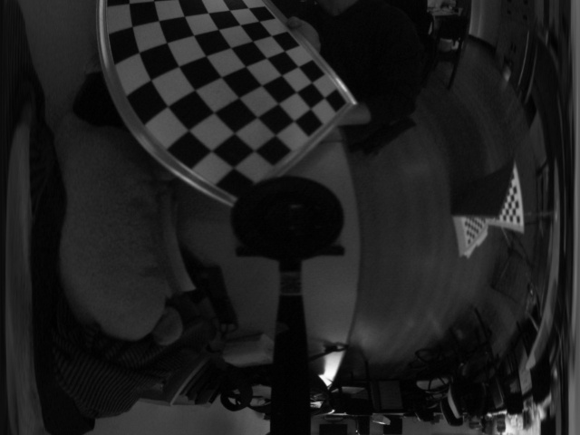
The first step to calibrate camera is to get a calibration pattern and take some photos. Several kinds of patterns are supported by OpenCV, like checkerborad and circle grid. A new pattern named random pattern can also be used, you can refer to opencv_contrib/modules/ccalib for more details.
Next step is to extract corners from calibration pattern. For checkerboard, use OpenCV function cv::findChessboardCorners; for circle grid, use cv::findCirclesGrid, for random pattern, use the randomPatternCornerFinder class in opencv_contrib/modules/ccalib/src/randomPattern.hpp. Save the positions of corners in images in a variable like imagePoints. The type of imagePoints may be std::vector<std::vector<cv::Vec2f>>, the first vector stores corners in each frame, the second vector stores corners in an individual frame. The type can also be std::vector<cv::Mat> where the cv::Mat is CV_32FC2.
Also, the corresponding 3D points in world (pattern) coordinate are required. You can compute they for yourself if you know the physical size of your pattern. Save 3D points in objectPoints, similar to imagePoints, it can be std::vector<std::vector<Vec3f>> or std::vector<cv::Mat> where cv::Mat is of type CV_32FC3. Note the size of objectPoints and imagePoints must be the same because they are corresponding to each other.
Another thing you should input is the size of images. The file opencv_contrib/modules/ccalib/tutorial/data/omni_calib_data.xml stores an example of objectPoints, imagePoints and imageSize. Use the following code to load them:
Then define some variables to store the output parameters and run the calibration function like:
K, xi, D are internal parameters and rvecs, tvecs are external parameters that store the pose of patterns. All of them have depth of CV_64F. The xi is a single value variable of Mei's model. idx is a CV_32S Mat that stores indices of images that are really used in calibration. This is due to some images are failed in the initialization step so they are not used in the final optimization. The returned value rms is the root mean square of reprojection errors.
The calibration supports some features, flags is a enumeration for some features, including:
Your can specify flags to fix parameters during calibration. Use 'plus' operator to set multiple features. For example, CALIB_FIX_SKEW+CALIB_FIX_K1 means fixing skew and K1.
criteria is the stopping criteria during optimization, set it to be, for example, cv::TermCriteria(cv::TermCriteria::COUNT + cv::TermCriteria::EPS, 200, 0.0001), which means using 200 iterations and stopping when relative change is smaller than 0.0001.
Stereo calibration is to calibrate two cameras together. The output parameters include camera parameters of two cameras and the relative pose of them. To recover the relative pose, two cameras must observe the same pattern at the same time, so the objectPoints of two cameras are the same.
Now detect image corners for both cameras as discussed above to get imagePoints1 and imagePoints2. Then compute the shared objectPoints.
An example of of stereo calibration data is stored in opencv_contrib/modules/ccalib/tutorial/data/omni_stereocalib_data.xml. Load the data by
Then do stereo calibration by
Here rvec and tvec are the transform between the first and the second camera. rvecsL and tvecsL are the transforms between patterns and the first camera.
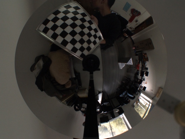
Omnidirectional images have very large distortion, so it is not compatible with human's eye balls. For better view, rectification can be applied if camera parameters are known. Here is an example of omnidirectional image of 360 degrees of horizontal field of view.
After rectification, a perspective like view is generated. Here is one example to run image rectification in this module:
The variable distorted and undistorted are the origional image and rectified image perspectively. K, D, xi are camera parameters. KNew and new_size are the camera matrix and image size for rectified image. flags is the rectification type, it can be:
The following four images are four types of rectified images discribed above:
It can be observed that perspective rectified image perserves only a little field of view and is not goodlooking. Cylindrical rectification preserves all field of view and scene is unnatural only in the middle of bottom. The distortion of stereographic in the middle of bottom is smaller than cylindrical but the distortion of other places are larger, and it can not preserve all field of view. For images with very large distortion, the longitude-latitude rectification does not give a good result, but it is available to make epipolar constraint in a line so that stereo matching can be applied in omnidirectional images.
Note: To have a better result, you should carefully choose Knew and it is related to your camera. In general, a smaller focal length leads to a smaller field of view and vice versa. Here are recommonded settings.
For RECTIFY_PERSPECTIVE
For RECTIFY_CYLINDRICAL, RECTIFY_STEREOGRAPHIC, RECTIFY_LONGLATI
Maybe you need to change (u0, v0) to get a better view.
Stereo reconstruction is to reconstruct 3D points from a calibrated stereo camera pair. It is a basic problem of computer vison. However, for omnidirectional camera, it is not very popular because of the large distortion make it a little difficult. Conventional methods rectify images to perspective ones and do stereo reconstruction in perspective images. However, the last section shows that recifying to perspective images lose too much field of view, which waste the advantage of omnidirectional camera, i.e. large field of view.
The first step of stereo reconstruction is stereo rectification so that epipolar lines are horizontal lines. Here, we use longitude-latitude rectification to preserve all filed of view, or perspective rectification which is available but is not recommended. The second step is stereo matching to get a disparity map. At last, 3D points can be generated from disparity map.
The API of stereo reconstruction for omnidrectional camera is omnidir::stereoReconstruct. Here we use an example to show how it works.
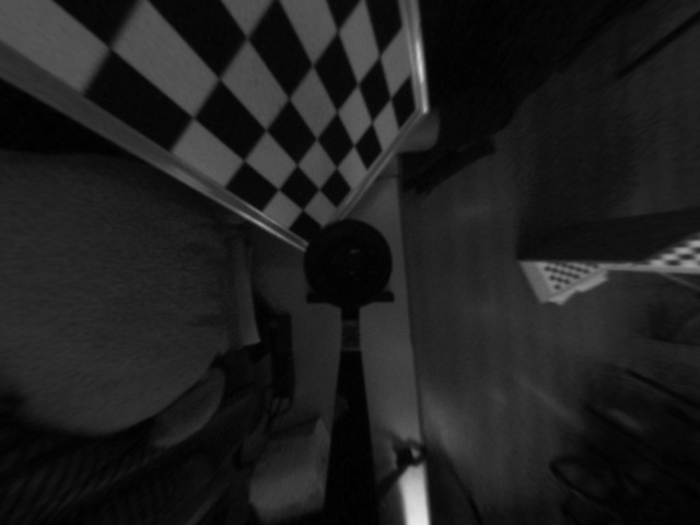
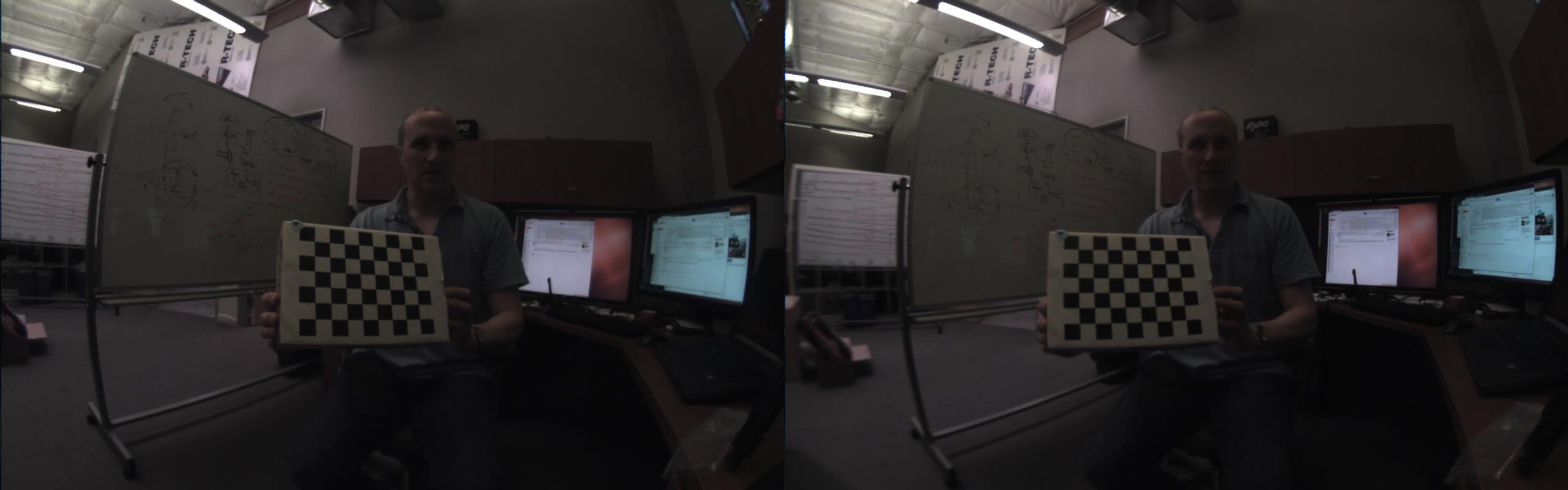
First, calibrate a stereo pair of cameras as describe above and get parameters like K1, D1, xi1, K2, D2, xi2, rvec, tvec. Then read two images from the first and second camera respectively, for instance, image1 and image2, which are shown below.
Second, run omnidir::stereoReconstruct like:
Here variable flag indicates the recectify type, only RECTIFY_LONGLATI(recommend) and RECTIFY_PERSPECTIVE make sense. numDisparities is the max disparity value and SADWindowSize is the window size of cv::StereoSGBM. pointType is a flag to define the type of point cloud, omnidir::XYZRGB each point is a 6-dimensional vector, the first three elements are xyz coordinate, the last three elements are rgb color information. Another type omnidir::XYZ means each point is 3-dimensional and has only xyz coordiante.
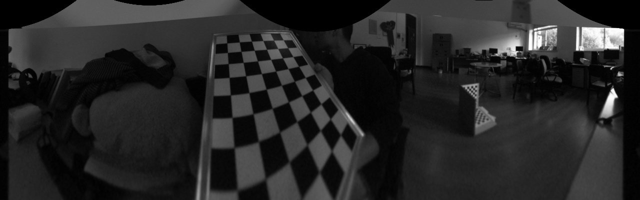
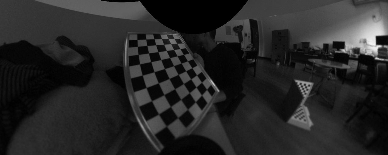
Moreover, imageRec1 and imagerec2 are rectified versions of the first and second images. The epipolar lines of them have the same y-coordinate so that stereo matching becomes easy. Here are an example of them:
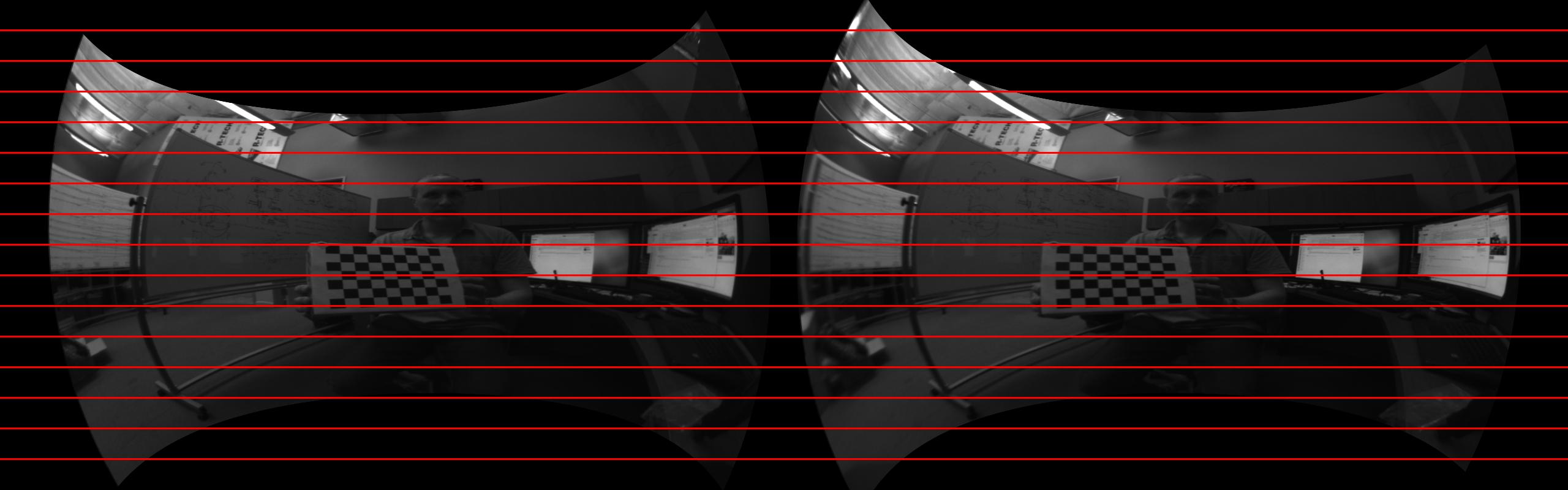
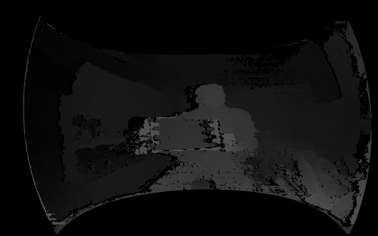
It can be observed that they are well aligned. The variable disMap is the disparity map computed by cv::StereoSGBM from imageRec1 and imageRec2. The disparity map of the above two images is:
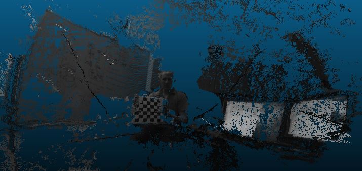
After we have disparity, we can compute 3D location for each pixel. The point cloud is stored in pointCloud, which is a 3-channel or 6-channel cv::Mat. We show the point cloud in the following image.
 1.8.12