Goal
In this tutorial you will learn how to:
- Apply two very common morphological operators: Erosion and Dilation. For this purpose, you will use the following OpenCV functions:
Interesting fact
- Note
- The explanation below belongs to the book Learning OpenCV by Bradski and Kaehler.
Morphological Operations
Dilation
- This operations consists of convolving an image \(A\) with some kernel ( \(B\)), which can have any shape or size, usually a square or circle.
- The kernel \(B\) has a defined anchor point, usually being the center of the kernel.
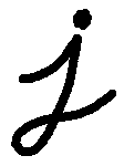
As the kernel \(B\) is scanned over the image, we compute the maximal pixel value overlapped by \(B\) and replace the image pixel in the anchor point position with that maximal value. As you can deduce, this maximizing operation causes bright regions within an image to "grow" (therefore the name dilation). Take the above image as an example. Applying dilation we can get:
The background (bright) dilates around the black regions of the letter.
To better grasp the idea and avoid possible confusion, in this other example we have inverted the original image such as the object in white is now the letter. We have performed two dilatations with a rectangular structuring element of size 3x3.

Left image: original image inverted, right image: resulting dilatation
The dilatation makes the object in white bigger.
Erosion
- This operation is the sister of dilation. It computes a local minimum over the area of given kernel.
- As the kernel \(B\) is scanned over the image, we compute the minimal pixel value overlapped by \(B\) and replace the image pixel under the anchor point with that minimal value.
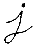
Analagously to the example for dilation, we can apply the erosion operator to the original image (shown above). You can see in the result below that the bright areas of the image (the background, apparently), get thinner, whereas the dark zones (the "writing") gets bigger.
In similar manner, the corresponding image results by applying erosion operation on the inverted original image (two erosions with a rectangular structuring element of size 3x3):

Left image: original image inverted, right image: resulting erosion
The erosion makes the object in white smaller.
Code
This tutorial's code is shown below. You can also download it here
#include <iostream>
Mat src, erosion_dst, dilation_dst;
int erosion_elem = 0;
int erosion_size = 0;
int dilation_elem = 0;
int dilation_size = 0;
int const max_elem = 2;
int const max_kernel_size = 21;
void Erosion( int, void* );
void Dilation( int, void* );
int main( int argc, char** argv )
{
CommandLineParser parser( argc, argv,
"{@input | ../data/chicky_512.png | input image}" );
{
cout << "Could not open or find the image!\n" << endl;
cout << "Usage: " << argv[0] << " <Input image>" << endl;
return -1;
}
createTrackbar(
"Element:\n 0: Rect \n 1: Cross \n 2: Ellipse",
"Erosion Demo",
&erosion_elem, max_elem,
Erosion );
&erosion_size, max_kernel_size,
Erosion );
createTrackbar(
"Element:\n 0: Rect \n 1: Cross \n 2: Ellipse",
"Dilation Demo",
&dilation_elem, max_elem,
Dilation );
&dilation_size, max_kernel_size,
Dilation );
Erosion( 0, 0 );
Dilation( 0, 0 );
return 0;
}
void Erosion( int, void* )
{
int erosion_type = 0;
if( erosion_elem == 0 ){ erosion_type =
MORPH_RECT; }
else if( erosion_elem == 1 ){ erosion_type =
MORPH_CROSS; }
Size( 2*erosion_size + 1, 2*erosion_size+1 ),
Point( erosion_size, erosion_size ) );
erode( src, erosion_dst, element );
imshow(
"Erosion Demo", erosion_dst );
}
void Dilation( int, void* )
{
int dilation_type = 0;
if( dilation_elem == 0 ){ dilation_type =
MORPH_RECT; }
else if( dilation_elem == 1 ){ dilation_type =
MORPH_CROSS; }
Size( 2*dilation_size + 1, 2*dilation_size+1 ),
Point( dilation_size, dilation_size ) );
dilate( src, dilation_dst, element );
imshow(
"Dilation Demo", dilation_dst );
}
Explanation
Most of the material shown here is trivial (if you have any doubt, please refer to the tutorials in previous sections). Let's check the general structure of the program:
- Load an image (can be BGR or grayscale)
- Create two windows (one for dilation output, the other for erosion)
- Create a set of two Trackbars for each operation:
- The first trackbar "Element" returns either erosion_elem or dilation_elem
- The second trackbar "Kernel size" return erosion_size or dilation_size for the corresponding operation.
- Every time we move any slider, the user's function Erosion or Dilation will be called and it will update the output image based on the current trackbar values.
Let's analyze these two functions:
- erosion:
void Erosion( int, void* )
{
int erosion_type = 0;
if( erosion_elem == 0 ){ erosion_type =
MORPH_RECT; }
else if( erosion_elem == 1 ){ erosion_type =
MORPH_CROSS; }
Size( 2*erosion_size + 1, 2*erosion_size+1 ),
Point( erosion_size, erosion_size ) );
erode( src, erosion_dst, element );
imshow(
"Erosion Demo", erosion_dst );
}
- The function that performs the erosion operation is cv::erode . As we can see, it receives three arguments:
- src: The source image
- erosion_dst: The output image
element: This is the kernel we will use to perform the operation. If we do not specify, the default is a simple 3x3 matrix. Otherwise, we can specify its shape. For this, we need to use the function cv::getStructuringElement :
Size( 2*erosion_size + 1, 2*erosion_size+1 ),
Point( erosion_size, erosion_size ) );
We can choose any of three shapes for our kernel:
- Rectangular box: MORPH_RECT
- Cross: MORPH_CROSS
- Ellipse: MORPH_ELLIPSE
Then, we just have to specify the size of our kernel and the anchor point. If not specified, it is assumed to be in the center.
- That is all. We are ready to perform the erosion of our image.
- Note
- Additionally, there is another parameter that allows you to perform multiple erosions (iterations) at once. However, We haven't used it in this simple tutorial. You can check out the reference for more details.
dilation:
The code is below. As you can see, it is completely similar to the snippet of code for erosion. Here we also have the option of defining our kernel, its anchor point and the size of the operator to be used.
void Dilation( int, void* )
{
int dilation_type = 0;
if( dilation_elem == 0 ){ dilation_type =
MORPH_RECT; }
else if( dilation_elem == 1 ){ dilation_type =
MORPH_CROSS; }
Size( 2*dilation_size + 1, 2*dilation_size+1 ),
Point( dilation_size, dilation_size ) );
dilate( src, dilation_dst, element );
imshow(
"Dilation Demo", dilation_dst );
}
Results
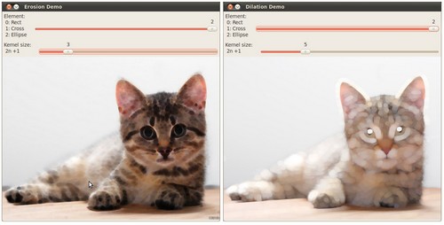
Compile the code above and execute it with an image as argument. For instance, using this image:
We get the results below. Varying the indices in the Trackbars give different output images, naturally. Try them out! You can even try to add a third Trackbar to control the number of iterations.


 1.8.12